Ceramic raw material stirring device

A technology of a stirring device and ceramic raw materials, which is applied in the field of ceramic product production, can solve the problems of quality influence of finished ceramics, inability to remove iron impurities, etc., and achieve the effect of convenient cleaning

Active Publication Date: 2020-09-08
唐山欧格仕智能卫浴有限公司
View PDF9 Cites 2 Cited by
  • Summary
  • Abstract
  • Description
  • Claims
  • Application Information

AI Technical Summary

Problems solved by technology

[0005] But in the process of practical application, metal impurities such as iron can be contained in the ceramic raw material, if iron impurity is not removed, the quality of finished ceramics has very big influence, in the process that ceramic raw material is stirred in above-mentioned prior art, There is a disadvantage that iron impurities in ceramic raw materials cannot be removed while stirring

Method used


Image

  • Ceramic raw material stirring device
  • Ceramic raw material stirring device
  • Ceramic raw material stirring device

Examples


Embodiment 1

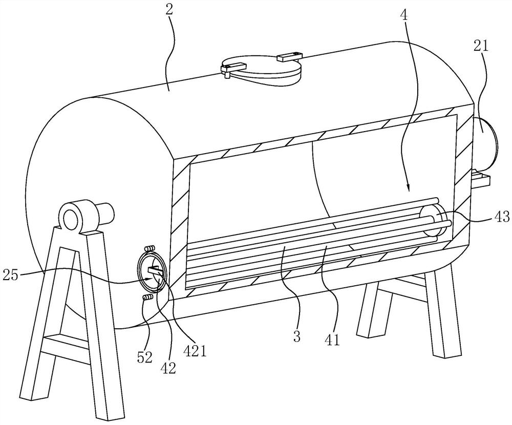
[0037] Embodiment one: if image 3 As shown, it is a ceramic raw material stirring device disclosed in the present invention, which includes a first connecting hole 25 provided at an eccentric position on a side of the mixing barrel body 2 away from the motor 21, and the first connecting hole 25 communicates with the inside of the mixing barrel body 2. . A magnet bar 3 passes through the first connection hole 25 , and the magnet bar 3 is inserted into the inside of the mixing tank body 2 and connected to the inner wall of the mixing tank body 2 through the connecting mechanism 4 .

[0038] Such as image 3 and Figure 4 As shown, the side of the mixing tank body 2 provided with the first connection hole 25 is connected with an end cover 51 through the dismounting mechanism 5. When the magnet bar 3 is inserted into the inside of the mixing tank body 2, the end cover 51 covers the first connection hole 25 (refer to Figure 5 ).

[0039] When the ceramic raw materials need t...

Embodiment 2

[0051] Embodiment two: a kind of ceramic raw material stirring device, such as Figure 6 and Figure 7 As shown, the difference from Embodiment 1 is that the first connecting block 42 is provided with a second connecting hole 422 passing through the first connecting block 42 along the axis direction of the magnet bar 3, and the shape of the second connecting hole 422 is arc-shaped. , the middle portion of the second connecting hole 422 is depressed downward.

[0052] A receiving plate 423 is inserted into the second connecting hole 422 , and the cross-sectional shape of the receiving plate 423 is the same as that of the second connecting hole 422 . The receiving plate 423 extends away from the side of the first connecting block 42 to close to the second connecting block 43 , and the side of the second connecting block 43 close to the receiving plate 423 is provided with a connecting groove 431 having the same shape as the second connecting hole 422 . When the receiving plate...


PUM


Abstract

The invention relates to the technical field of ceramic product production, and especially relates to a ceramic raw material stirring device. The device comprises a stirring barrel body, a first connecting hole communicated with the interior of the stirring barrel body is formed in the eccentric position of one side surface of the stirring barrel body, a magnet rod penetrates through the first connecting hole, is inserted into the stirring barrel body and is connected with the inner wall of the stirring barrel body through a connecting mechanism, and the side, provided with the first connecting hole, of the stirring barrel body is connected with an end cover for covering the first connecting hole through a detaching mechanism. The device has the effect of removing iron impurities in the ceramic raw material as much as possible.

Description

technical field [0001] The invention relates to the technical field of ceramic product production, in particular to a ceramic raw material stirring device. Background technique [0002] At present, in the process of making ceramic products, it is necessary to mix various raw materials for producing ceramics with water and then pass through a stirring device to stir evenly, and then filter the ceramic raw materials and other follow-up work after stirring evenly. [0003] Such as figure 1 and figure 2 As shown, the existing stirring device for ceramic raw materials includes a pair of support frames 1, and a mixing tank body 2 is rotatably connected between the pair of support frames 1, and the mixing tank body 2 is connected with a motor 21 that drives the mixing tank body 2 to rotate. . The surface of the mixing barrel body 2 is provided with a feed port 22 , and the feed port 22 is connected with a cover body 23 covering the feed port 22 . The surface of the mixing barr...

Claims


Application Information

Patent Timeline
Patent Type & Authority Applications(China)
IPC IPC(8): B01F9/06B03C1/02B01F29/63
CPCB03C1/02B01F29/63Y02P40/60
Inventor 赵云海
Owner 唐山欧格仕智能卫浴有限公司
Why Eureka
Try Eureka