
Stretch-bending forming technology and stretch-bending equipment for anti-collision beams

A stretch bending forming and anti-collision technology, which is applied in the field of production and manufacturing, can solve problems such as bending, cracking and wrinkling, side bending and twisting of profiles, and springback should not be eliminated, so as to achieve the effects of safe use, stability assurance and convenient operation

Inactive Publication Date: 2020-09-08
明达铝业科技(太仓)有限公司
View PDF10 Cites 0 Cited by
  • Summary
  • Abstract
  • Description
  • Claims
  • Application Information

AI Technical Summary

Problems solved by technology

At present, other bending pipe forms have certain limitations, and are not suitable for bending forming of such beams, and cannot meet the quality requirements after plastic forming.
For example, the process of bending and bending cannot process the profile with a large bending radius and an overall arc, and the springback should not be eliminated, and the stability of the product cannot be guaranteed.
Although the rolling bending method can be used, due to the large cross-section of the profile and the asymmetric cross-section of the profile, the profile is prone to side bending and twisting after rolling, and due to the large cross-section of the profile, it also has certain restrictions on the tonnage of the rolling bending equipment. Requirements, so it is most suitable to use stretch bending equipment to process this type of material, but there will also be problems such as bending, cracking and wrinkling during the stretch bending process

Method used


Image

  • Stretch-bending forming technology and stretch-bending equipment for anti-collision beams

Examples


Embodiment Construction

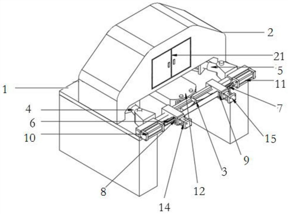
[0027] The present invention will be further explained below in conjunction with the accompanying drawings and specific embodiments.

[0028] Embodiments of the present invention are described in detail below, examples of which are shown in the drawings, wherein the same or similar reference numerals designate the same or similar elements or elements having the same or similar functions throughout. The embodiments described below by referring to the figures are exemplary and are intended to explain the present invention and should not be construed as limiting the present invention.

[0029] In describing the present invention, it should be understood that the terms "center", "longitudinal", "transverse", "length", "width", "thickness", "upper", "lower", "front", " The orientations or positional relationships indicated by "rear", "left", "right", "vertical", "horizontal", "top", "bottom", "inner", "clockwise", "counterclockwise" are based on the attached The orientation or pos...


PUM


Abstract

The invention discloses a stretch-bending forming technology for anti-collision beams. The technology includes the following steps that (1) special mandrels, a positioning cavity and clamping blocks are designed according to different cross beams and are mounted on a stretch-bending machine; (2) machining parameters of stretch-bending equipment are adjusted; (3) after positioning by the aid of themiddle positioning cavity, a button is started, and the mandrels are automatically inserted into a profile; (4) the two ends of the profile are clamped by the aid of two-end clamping switches; (5) driving stretch-bending arms begin to perform backward stretch-bending on the profile with the middle section used as the reference point and can stop automatically after one-time bending, the clampingblocks on the left and right sides loosen the profile, then the moving mandrels are controlled by extending oil cylinders to be inserted forwards, the clamping blocks on the left and right sides clampthe profile to start second-time bending, and the process is repeated four times until last-time stretch-bending forming; (6) after stretch-bending forming, a restoration button is pressed, and the next profile is machined; and (7) steps (3)-(6) are repeated for cycle operation and production. According to the technology, the bending angle can be adjusted at will, the desired effects of finishedproducts can be achieved, and the problems that profiles cannot be formed or are not easy to form, are prone to lateral bending or distortion, are broken or wrinkled after being bent and the like dueto the fact that the profiles are large are solved.

Description

technical field [0001] The invention belongs to the field of production and manufacturing, and in particular relates to a stretch bending forming process of an anti-collision beam and stretch bending equipment thereof. Background technique [0002] The automotive industry is a pillar industry in the global manufacturing industry. With the development of science and technology and the continuous growth of market demand, the frequency of car updates is accelerating, and the important factor affecting car updates is the update of the function and appearance of car panels. Automobile anti-collision beam is an important part of automobile panels, an important device for automobiles to absorb collision energy, and plays an important role in automobile production. [0003] Since the forming process of the automobile beam is relatively complicated, it is a complex shaping process with large deflection and large deformation. This kind of curved profiles has different shapes and var...

Claims


Application Information

Patent Timeline
Patent Type & Authority Applications(China)
IPC IPC(8): B21D9/16B21D43/00
CPCB21D9/16B21D43/003
Inventor 郑博文
Owner 明达铝业科技(太仓)有限公司
Learn More