A kind of iron shoe device for rolling trains

A technology of iron shoes and train sets, which is applied in the field of rail transit, can solve the problems of iron shoe devices detached from rails, extended braking distance of train sets, and large loss of iron shoe devices, so as to increase friction, improve stability, and prevent waste Effect

Active Publication Date: 2021-07-23
义乌市万博创意设计有限公司
View PDF8 Cites 0 Cited by
  • Summary
  • Abstract
  • Description
  • Claims
  • Application Information

AI Technical Summary

Problems solved by technology

[0005] 1. When the car group is slipping, due to the large inertia, the toe 3 part of the shoe is quickly stressed at the moment of contact with the iron shoe device. At this time, the shoe tail 6 part will be tilted once at a very fast speed, which is very fast. It is easy to cause the iron shoe device to break away from the rails, causing the brakes to not be released in time, and due to the increase in the braking distance, it hits the car group parked before, causing huge damage;
[0006] 2. Factors affecting the sliding operation include human factors and weather factors. Once it encounters rainy and snowy weather, the rain and snow on the rails will act as a lubricant, which will prolong the braking distance of the train group, and may also cause a crash accident;
[0007] 3. Since the toe 3 and the wheel of the train are the key contact parts, the toe 3 is a vulnerable part, and because the existing toe 3 and the iron shoe device are all in one structure, when the toe 3 of the sole 1 In the event of severe wear, it would be too costly to replace the entire iron shoe unit

Method used


Image

  • A kind of iron shoe device for rolling trains
  • A kind of iron shoe device for rolling trains
  • A kind of iron shoe device for rolling trains

Examples


Embodiment Construction

[0031] The following will clearly and completely describe the technical solutions in the embodiments of the present invention with reference to the accompanying drawings in the embodiments of the present invention. Obviously, the described embodiments are only some, not all, embodiments of the present invention. Based on the embodiments of the present invention, all other embodiments obtained by persons of ordinary skill in the art without making creative efforts belong to the protection scope of the present invention.

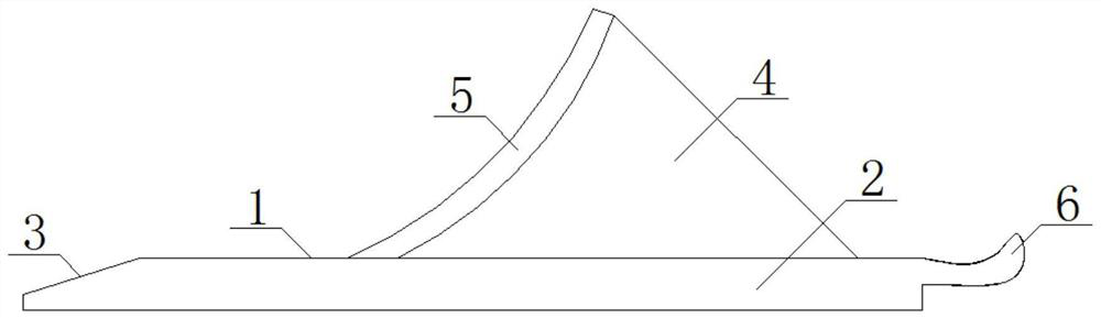
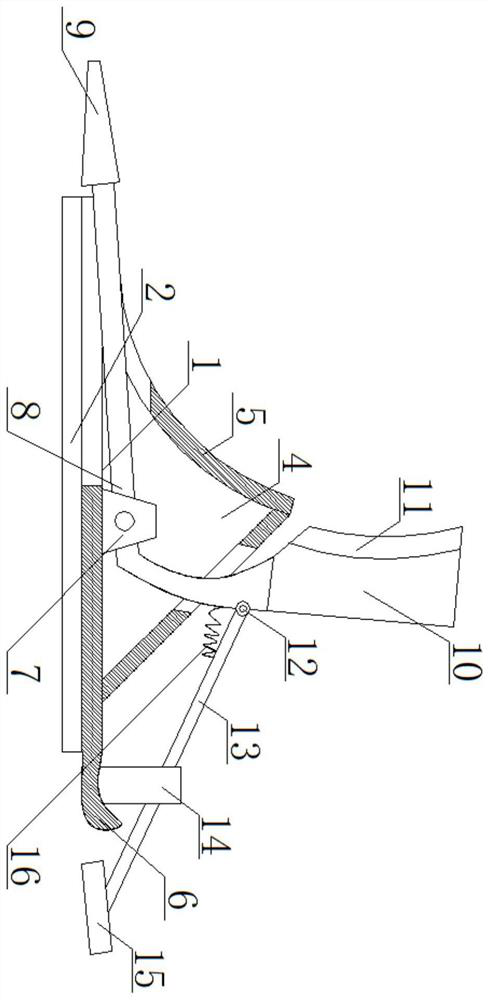
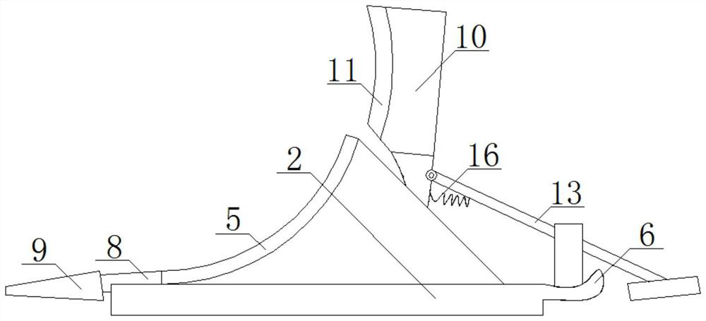
[0032] see Figure 2-10 , an iron shoe device for rolling and releasing a car group, comprising a shoe sole 1, a vertical plate 4 and a shoe tail 6, the top of the shoe sole 1 is welded with a rotating seat 7 in the inner cavity of the vertical plate 4, and the rotating seat 7 is movably installed with a warp through a pin shaft. Rod 8, the left end of warping bar 8 is fixedly installed with detachable shoe shovel 9, and warping bar 8 is positioned at the righ...


PUM


Abstract

The invention relates to the technical field of rail transit, and discloses an iron shoe device for rolling trains, including a shoe sole, a vertical plate and a shoe tail. A warping bar is movably installed through the pin shaft, and a detachable shoe shovel is fixedly installed on the left end of the warping bar, and a counterweight is arranged on the right side of the warping bar at the rotating seat. The iron shoe device for rolling and unloading the car group is equipped with a detachable shoe shovel that can be lifted and linked with a counterweight. The steel rail contacts and slides, and at the same time, the movable pedal on the linkage counterweight is close to the wheel to resist the wheel, ensuring that the detachable shoe shovel, counterweight and shoe tail are stressed at the same time, and at the same time, the iron shoe device The stress point of the shoe is moved from the tip of the shoe to the middle of the iron shoe device, preventing the tail of the shoe from lifting due to uneven force, and improving the stability and safety of the existing iron shoe device.

Description

technical field [0001] The invention relates to the technical field of rail transit, in particular to an iron shoe device for rolling trains. Background technique [0002] The iron shoe is a kind of equipment for rail transit. Its function can be anti-slip or brake. In the anti-slip operation, it is only necessary to place the iron shoe on the wheel when the train group is stationary to prevent the train group from slipping backwards. Iron shoes are relatively complicated when braking. [0003] see figure 1 , the existing brake iron shoe structure includes a sole 1, the front and back of the sole 1 are provided with a skirt 2, the left end of the sole 1 is provided with a toe 3, the top of the sole 1 is welded with a vertical plate 4, and the left side of the vertical plate 4 The tread 5 is welded on the side, and the right end of the shoe sole 1 is provided with a shoe tail 6; when the train group slips, only the shoe sole 1 of the iron shoe device is placed on the rail, ...

Claims


Application Information

Patent Timeline
Patent Type & Authority Patents(China)
IPC IPC(8): B61H7/10E01H8/00E01H8/06
CPCB61H7/10E01H8/00E01H8/06
Inventor 罗远菊
Owner 义乌市万博创意设计有限公司
Why Eureka
Try Eureka