Abalone can bottle opening device

A technology for abalone cans and mounting plates, which is applied to electric operating devices, packaging, bottle filling, etc. It can solve the problems of no fixed unit, inconvenient use, and inability to open cans of other shapes.

Inactive Publication Date: 2020-09-08
林贞妹
7 Cites 0 Cited by

AI-Extracted Technical Summary

Problems solved by technology

[0003] The existing application number is CN201820710043.2, which discloses a canned abalone bottle opening device. The motor placed in the fixed groove opened by the installation head drives the first gear to rotate, and the rotating first gear drives the second gear to rotate, and the rotating second gear drives the rotation of the second gear. The gear drives the connecting rod and the support rod fixed at the bottom of the connecting rod to rotate. The limit plate contained in the connecting rod cooperates with the fixed horizontal plate to limit the range of motion of the connecting rod and the supporting rod. The supporting rod drives the screw cap fixedly connected at the bottom to rotate. The blade at the bottom i...

Method used

Uncork unit 3: comprise connecting plate 31, sucker 32, connecting column 33, block 34 and drill bit 35, connecting plate 31 places the extension end of first electro-hydraulic push rod 2, connecting plate 31 lower surface The left and right ends are all provided with suction cups 32, and the middle part of the connecting plate 31 lower surface is provided with a connecting column 33, and the side wall of the connecting column 33 is provided with two installation grooves, and the second electro-hydraulic push rod 15 is arranged in the installation groove, and the second The protruding end of the electro-hydraulic push rod 15 is provided with a stopper 34, which is slidingly connected between the stopper 34 and the connecting column 33, and the lower end of the connecting column 33 is provided with a drill bit 35. When in use, the first electro-hydraulic push rod 2 is opened, The protruding end of the first electro-hydraulic push rod 2 can drive the connecting plate 31 to move downward, and the connecting plate 31 can drive the suction cup 32 to move downward. The suction cup 32 can be used to ab...

Abstract

The invention discloses an abalone can bottle opening device. The fixed end of a first electric-hydraulic pusher is fixedly connected with a mounting plate, and suction cups are arranged at the left end and the right end of the lower surface of a connecting plate. A connecting column is arranged in the middle of the lower surface of the connecting plate, and a second electric-hydraulic pusher is arranged in a mounting groove. A check block is arranged at the stretching end of the second electric-hydraulic pusher. The check block and the connecting column are slidably connected, and a drill bitis arranged at the lower end of the connecting column. Two third electric-hydraulic pusher is are arranged on the inner side wall of the lower end of a side plate, a fastening plate is arranged between the stretching ends of the two corresponding third electric-hydraulic pushers, and the fastening plate is a flexible rubber plate. Cans in various shapes can be opened, practicality is achieved, manpower can be replaced for fixing the cans in the bottle opening process, and use is convenient.

Application Domain

Bottle/container closurePower operated devices +1

Technology Topic

Drill bitStructural engineering +3

Image

  • Abalone can bottle opening device
  • Abalone can bottle opening device
  • Abalone can bottle opening device

Examples

  • Experimental program(1)

Example Embodiment

[0027] The technical solutions in the embodiments of the present invention will be clearly and completely described below in conjunction with the accompanying drawings in the embodiments of the present invention. Obviously, the described embodiments are only a part of the embodiments of the present invention, rather than all the embodiments. Based on the embodiments of the present invention, all other embodiments obtained by those of ordinary skill in the art without creative work shall fall within the protection scope of the present invention.
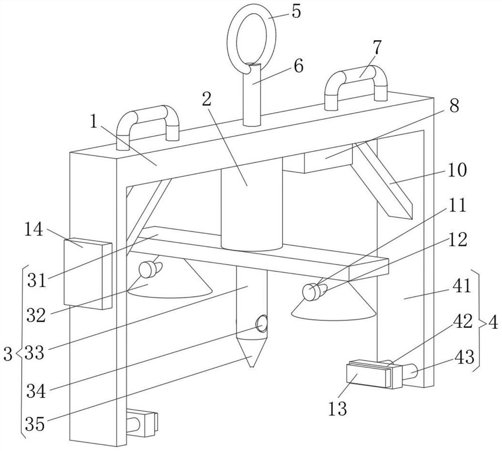
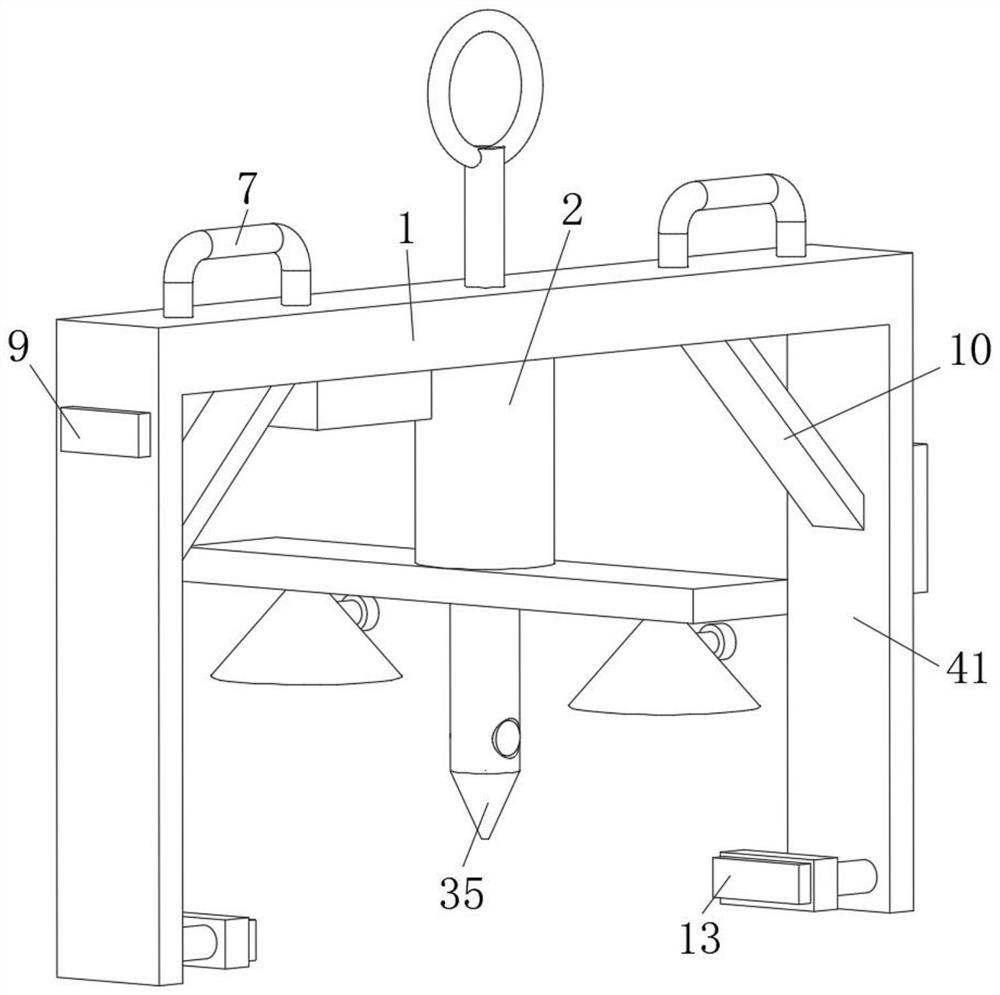
[0028] See Figure 1-3 , The present invention provides a technical solution: a bottle opening device for canned abalone, comprising a mounting plate 1, a bottle opening unit 3 and a fixing unit 4;
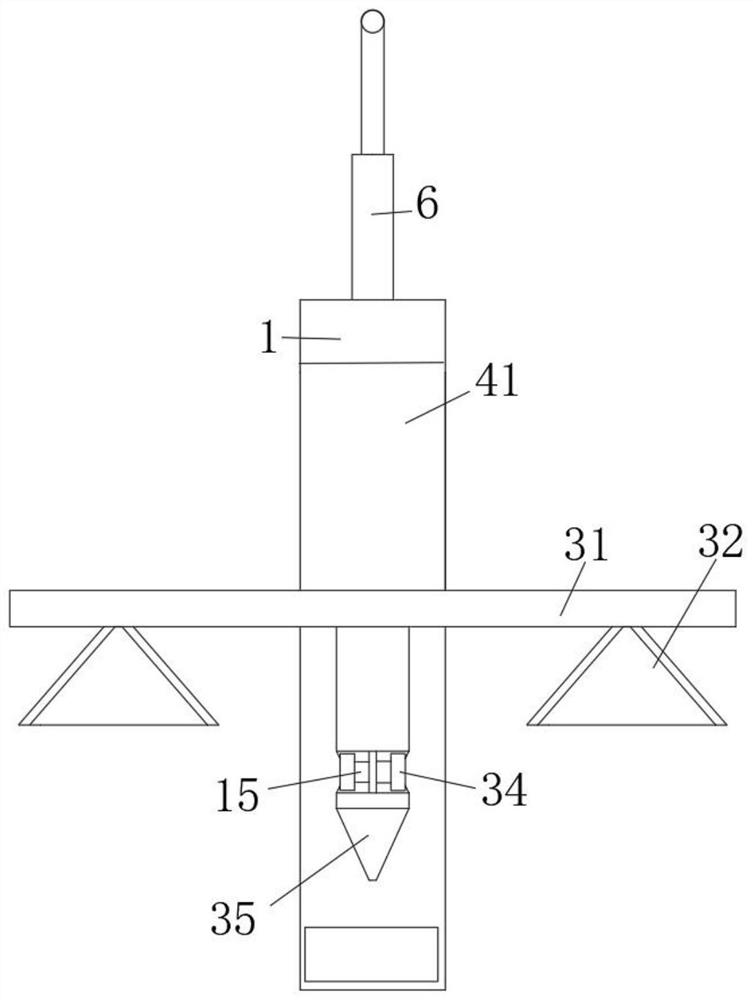
[0029] Mounting plate 1: A first electro-hydraulic push rod 2 is provided on the lower surface, and the fixed end of the first electro-hydraulic push rod 2 is fixedly connected to the mounting plate 1;
[0030] Bottle opening unit 3: includes a connecting plate 31, a suction cup 32, a connecting column 33, a stop 34, and a drill 35. The connecting plate 31 is placed on the extension end of the first electro-hydraulic push rod 2, and the left and right ends of the lower surface of the connecting plate 31 Each is provided with a suction cup 32, the middle of the lower surface of the connecting plate 31 is provided with a connecting column 33, the side wall of the connecting column 33 is provided with two installation grooves, and a second electro-hydraulic push rod 15 is provided in the installation groove. The extension end of the rod 15 is provided with a stopper 34. The stopper 34 is slidably connected to the connecting column 33. The lower end of the connecting column 33 is provided with a drill bit 35. When in use, the first electro-hydraulic push rod 2 is turned on, The protruding end of the liquid push rod 2 can drive the connecting plate 31 to move downward, and the connecting plate 31 can drive the suction cup 32 to move downward. The suction cup 32 can absorb the cap of the can, and the connecting column 33 can drive the drill 35 to move downward, thereby The drill bit 35 can penetrate the bottle cap of the can and be placed inside the can, and then open the second electro-hydraulic push rod 15. The extended end of the second electro-hydraulic push rod 15 can drive the stopper 34 to move outward along the installation groove, and then open The first electro-hydraulic push rod 2 retracts the first electro-hydraulic push rod 2 so that the cap of the can can be moved upward through the suction cup 32 and the stopper 34, so that the bottle can be opened. Use the suction cup 32 and the stopper 34 to pair Pulling the bottle cap instead of cutting the blade to open the bottle, so that cans of various shapes can be opened, which is practical;
[0031] The fixing unit 4: includes a side plate 41, a fastening plate 42 and a third electro-hydraulic push rod 43. The side plates 41 are two pieces, which are respectively placed on the front and rear ends of the mounting plate 1, and the inner side walls of the lower end of the side plate 41 are both provided There are two third electro-hydraulic push rods 43. A fastening plate 42 is provided between the extended ends of the corresponding two third electro-hydraulic push rods 43. The fastening plate 42 is a flexible rubber plate. When opening the bottle , Open the third electro-hydraulic push rod 43, the protruding end of the third electro-hydraulic push rod 43 can drive the fastening plate 42 to move forward, and the squeezing action of the third electro-hydraulic push rod 43 can perform Fixed, when the suction cup 32 and the stopper 34 pull the bottle cap, it can prevent the shell from moving with the cap, so that the can can be fixed instead of manpower during the bottle opening process, which is more convenient to use;
[0032] Among them, it also includes a control switch group 9, installed on the outer side wall of the side plate 41, and the output end of the control switch group 9 is electrically connected to the first electro-hydraulic push rod 2, the second electro-hydraulic push rod 15 and the third electro-hydraulic push rod 43 的input terminal.
[0033] Among them, it also includes a hanging ring 5 and a connecting rod 6. The connecting rod 6 is placed on the upper surface of the mounting plate 1, and the upper end of the connecting rod 6 is provided with a hanging ring 5, which can be used to hang the mounting plate 1.
[0034] There are two handles 7 in number, and they are all placed on the upper surface of the mounting board 1. The two ends of the handle 7 are rotatably connected with the mounting board 1, which can be used to conveniently handle the mounting board 1.
[0035] Among them, a battery 8 is also included, which is installed on the lower surface of the mounting board 1. The output terminal of the battery 8 is electrically connected to the input terminal of the control switch group 9 and can be used to provide electric energy.
[0036] Among them, it also includes a reinforcing plate 10, the number is two, and they are respectively placed on the inner side walls of the two side plates 41, the reinforcing plate 10, the side plate 41 and the mounting plate 1 form a triangle, which can be used to increase the side plate 41 stability.
[0037] Among them, it also includes a solenoid valve 11 and a trachea 12. There are two trachea 12, which are respectively placed on the side walls of the two suction cups 32. One end of the trachea 12 is connected to the suction cup 32, and the other end of the trachea 12 is provided with a solenoid valve 11. The input end of 11 is electrically connected to the output end of the control switch group 9 and can be used to pass air into the suction cup 32.
[0038] Among them, the anti-skid pad 13 is also included, the number is two, and they are respectively placed on the inner side walls of the two fastening plates 42 to further fix the shell.
[0039] Among them, a cleaning box 14 is also included, which is installed on the outer side wall of the side plate 41. A cleaning cloth is provided in the cleaning box 14 to clean the drill 35.
[0040] When in use: open the first electro-hydraulic push rod 2, the protruding end of the first electro-hydraulic push rod 2 can drive the connecting plate 31 to move down, the connecting plate 31 can drive the suction cup 32 to move down, and the suction cup 32 can absorb cans The connecting rod 33 can drive the drill bit 35 to move downward, so that the drill bit 35 can penetrate the bottle cap of the can and be placed inside the can, and then open the second electro-hydraulic push rod 15. The output end can drive the stopper 34 to move outward along the installation groove, and then open the first electro-hydraulic push rod 2 to retract the first electro-hydraulic push rod 2 so that the cap of the can can be driven upward through the suction cup 32 and the stop 34 Move, so that the bottle can be opened. The suction cup 32 and the stopper 34 are used to pull the bottle cap instead of cutting the blade to open the bottle, so that cans of various shapes can be opened. It is practical. When opening the bottle , Open the third electro-hydraulic push rod 43, the protruding end of the third electro-hydraulic push rod 43 can drive the fastening plate 42 to move forward, and the squeezing action of the third electro-hydraulic push rod 43 can perform Fixed, when the suction cup 32 and the stopper 34 pull the bottle cap, it can prevent the shell from moving with the cap, so that the can can be fixed instead of manpower during the bottle opening process, which is more convenient to use.
[0041] It is worth noting that the first electro-hydraulic push rod 2, the second electro-hydraulic push rod 15 and the third electro-hydraulic push rod 43 disclosed in this embodiment can adopt the model ANT-03, and the core chip of the control switch group 9 is selected It is a PLC single-chip microcomputer, the specific model is Siemens S7-200, the control switch group 9 controls the first electro-hydraulic push rod 2, the second electro-hydraulic push rod 15 and the third electro-hydraulic push rod 43 to work using methods commonly used in the prior art .
[0042] Although the embodiments of the present invention have been shown and described, those of ordinary skill in the art can understand that various changes, modifications, and substitutions can be made to these embodiments without departing from the principle and spirit of the present invention. And variations, the scope of the present invention is defined by the appended claims and their equivalents.

PUM

no PUM

Description & Claims & Application Information

We can also present the details of the Description, Claims and Application information to help users get a comprehensive understanding of the technical details of the patent, such as background art, summary of invention, brief description of drawings, description of embodiments, and other original content. On the other hand, users can also determine the specific scope of protection of the technology through the list of claims; as well as understand the changes in the life cycle of the technology with the presentation of the patent timeline. Login to view more.
Why Eureka
Try Eureka