
Optical fiber terminal box

A terminal box and optical fiber technology, applied in the field of communication, can solve the problems of short circuit or open circuit of wiring pigtails, affecting the safe use of optical fiber terminal boxes, unstable installation of optical cables, etc., to achieve the effect of improving convenience and speed.

Inactive Publication Date: 2020-09-08
安徽易知谷信息科技有限公司
View PDF0 Cites 2 Cited by
  • Summary
  • Abstract
  • Description
  • Claims
  • Application Information

AI Technical Summary

Problems solved by technology

[0004] Although the above content fixes the outdoor optical cable well, it is convenient to use the fast cold connection of optical fiber; but when the optical fiber terminal box is used in a mountainous area with strong wind and is used to build an outdoor tent optical fiber, the existing optical fiber terminal box Most of the redundant optical cables are bundled into the box with adhesive tape or the structure of the above-mentioned patent. When the optical fiber terminal box vibrates for a long time and a large wind force enters the box, the installation of the redundant optical cables will be unstable and scattered, and then It will cause the distribution pigtail connected to the adapter to be short-circuited or disconnected, which will affect the safe use of the optical fiber terminal box

Method used


Image

  • Optical fiber terminal box
  • Optical fiber terminal box
  • Optical fiber terminal box

Examples


Embodiment approach

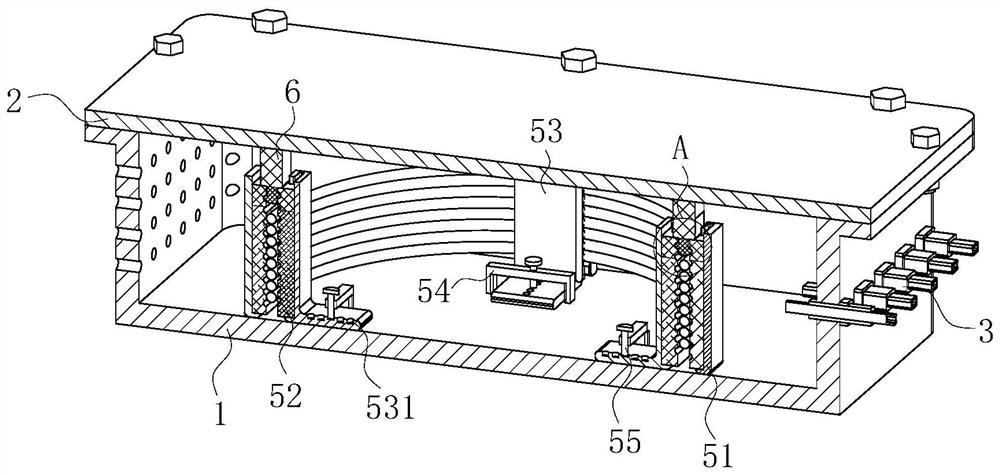
[0026] As an embodiment of the present invention, a plurality of elastic extruding blocks 6 are fixedly arranged in the circumferential direction of the inner wall of the bottom end of the lid 2, and the bottom ends of the plurality of elastic extruding blocks 6 are all provided with elastic blocks 7; The sliding of the above-mentioned elastic block 7 is inserted between the symmetrically arranged rubber snap strips 52; during operation, when the box cover 2 is fixed to the box body 1 by bolts and threads, the elastic extrusion set in the circumferential direction of the bottom end surface of the box cover 2 The block 6 will be squeezed and attached to the upper end surface of the rubber engaging strip 52, and the elastic block 7 will be inserted between the symmetrically arranged rubber engaging strips 52, so that the elastic extrusion block 6 can press against the rubber engaging strip 52 fixed, and at the same time, the elastic block 7 can limit and engage the optical cable ...


PUM


Abstract

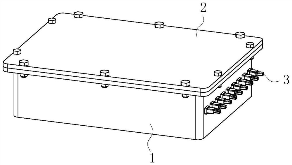
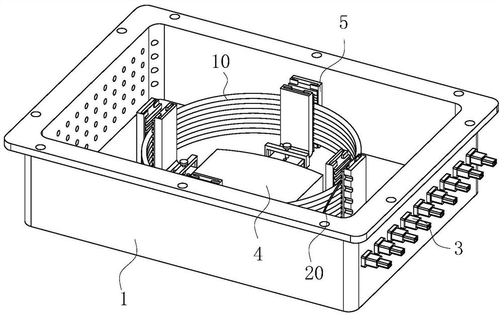
The invention belongs to the technical field of communication, and particularly relates to an optical fiber terminal box. The box comprises a box body, a box cover and an adapter. The box cover is fixed to the upper end of the box body through bolts, and the adapter is installed on the side wall of the box body. A fuse box is installed in the box body. A plurality of optical cable arrangement mechanisms are uniformly arranged in the box body in a circumferential direction, and the optical cable arrangement mechanisms are used for arranging optical cables stacked in the box body; a plurality offixed barrier strips are fixedly arranged in a circumferential direction in the box body, and rubber clamping strips are arranged on the inner side walls of the fixed barrier strips; a rubber clamping strip is mounted on the side wall of an L-shaped sliding strip; a U-shaped limiting frame is fixed to the bottom of the box body, an L-shaped sliding strip is arranged in the U-shaped limiting framein a sliding mode, and a threaded hole is formed in the U-shaped limiting frame. A plurality of fixing screw holes are uniformly formed in the horizontal plane of one side of the L-shaped sliding strip and are aligned with the threaded holes in a sliding manner. The redundant optical cables can be conveniently, safely and stably arranged in the box body through the plurality of optical cable arrangement mechanisms.

Description

technical field [0001] The invention belongs to the technical field of communication, in particular to an optical fiber terminal box. Background technique [0002] Because optical fiber communication has the advantages of large capacity, long distance and anti-electromagnetic interference, it is more suitable for the future human needs for large amount of information and high precision, and the low price enables the transmission medium of optical fiber to be widely promoted. At present, optical fiber network has been gradually used in households. The installation of fiber-to-the-home usually includes the installation of the fiber terminal box ATB and the installation of the optical network terminal ONT. [0003] The Chinese patent discloses a FTTH optical fiber connection terminal box, the application number is 2009100541779, the front end of the box body has an outdoor optical cable lead-in hole, the bottom plate below the lead-in hole has an outdoor optical cable fixing b...

Claims


Application Information

Patent Timeline
IPC IPC(8): G02B6/44
CPCG02B6/4446G02B6/4471
Inventor 许良云刘振
Owner 安徽易知谷信息科技有限公司
Learn More