Integrated supporting roller device

A support roller, integrated technology, applied in the direction of support structure installation, data centers, servers, etc., can solve problems such as troublesome stability, limited support strength, electrostatic floor damage, etc., to avoid excessive pressure, easy to fix, Easy to move effect

Pending Publication Date: 2020-09-08
南京南数数据运筹科学研究院有限公司
View PDF0 Cites 0 Cited by
  • Summary
  • Abstract
  • Description
  • Claims
  • Application Information

AI Technical Summary

Problems solved by technology

[0002] The server cabinets used in the server room generally need to install support rollers on the base of the server cabinet for the convenience of movement. However, the current server support roller solution is generally a simple rolling roller. When it needs to be moved, the cabinet can be directly pushed to the designated position manually. , if you need to fix the cabinet, you need to replace the rolling rollers with fixed support brackets or do not make any changes, and rely on the friction between the rollers and the ground to fix the cabinet. The above-mentioned cabinet method is troublesome and poor in stability in some cases; The static floor needs to be installed in the computer room. The support strength of the static floor itself is limited. When the server cabinet is placed on the top, the gravity of the entire cabinet and the servers placed on the cabinet will be transmitted to the static floor through the support rollers under the cabinet. Due to the support The contact surface between the rollers and the electrostatic floor is small. According to the pressure formula P=F / S, it can be known that the area where the classic floor and the rollers are in contact with is under great pressure. In this case, it is easy to cause damage to the electrostatic floor.

Method used


Image

  • Integrated supporting roller device
  • Integrated supporting roller device
  • Integrated supporting roller device

Examples


Embodiment

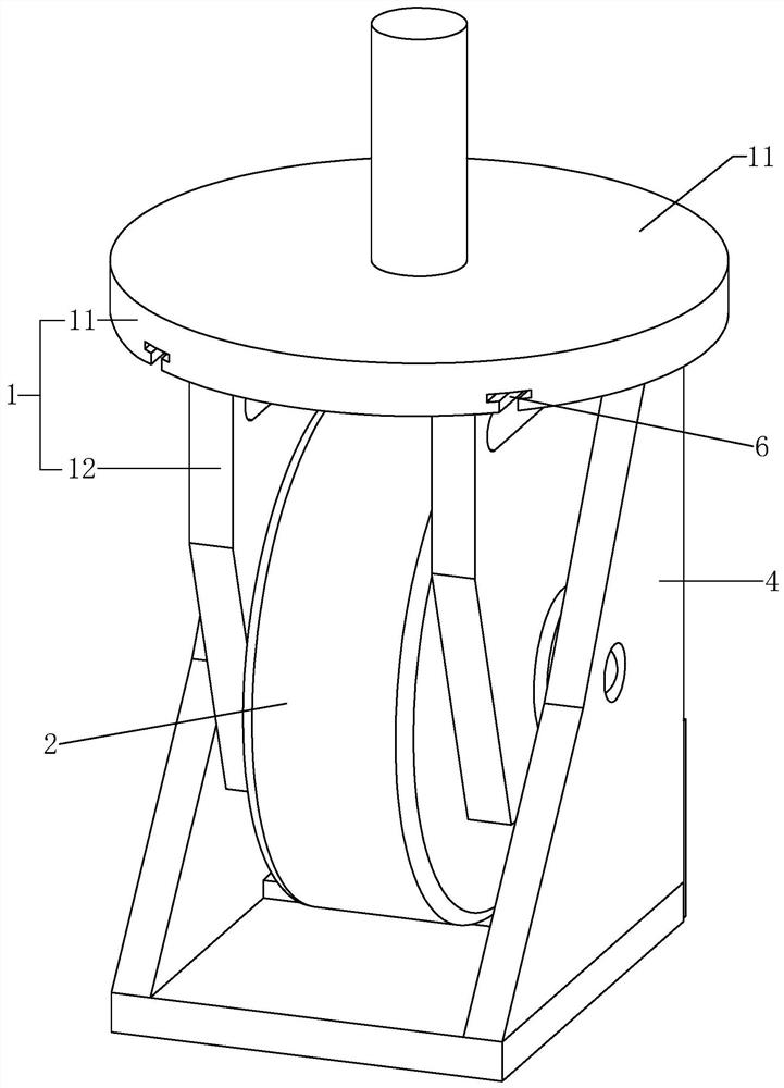
[0019] Example: Reference Figure 1-4 , an integrated supporting roller device, comprising: a bracket 1, a roller 2 and a variable fixed support part, wherein the bracket 1 is an integrally formed structure. The top of the support 1 is a rotating shaft, and below the rotating shaft is a fixedly connected disc 11, and the left and right side plates 12 are symmetrically and fixedly connected to the bottom of the disc 11. In particular, the left and right side plates 12 on the support 1 are provided with circular openings. The hole, the diameter of the through hole is consistent with the diameter of the through hole in the middle of the roller 2 and the diameter of the pin shaft 3, and the roller 2 is rotatably installed between the two side plates 12 through the pin shaft 3.

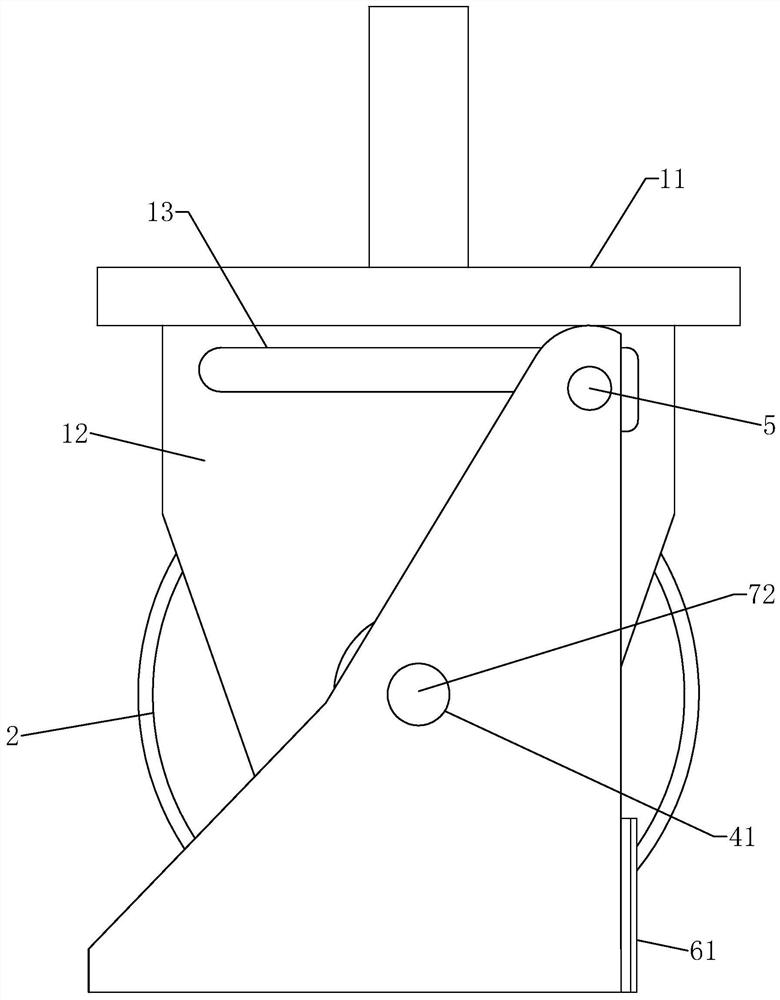
[0020] refer to Figure 1-4 , the two side plates 12 are symmetrically opened with horizontal sliding grooves 13 close to the disc 11, and the openings at the tails of the sliding grooves 13 become larger...

Embodiment 2

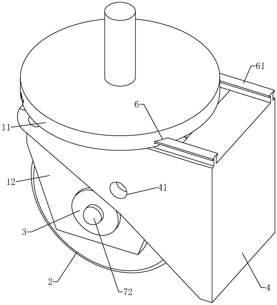
[0024] Embodiment 2, refer to image 3 and Figure 5 , an integrated support roller device, the difference from Embodiment 1 is that there is more structure for locking the U-shaped fixed support plate 4, when the U-shaped fixed support plate 4 enters the support state, the U-shaped fixed support is further improved Plate 4 Stability.

[0025] refer to image 3 and Figure 5 In the pin shaft 3, a mounting hole through the pin shaft 3 is provided along the axial direction of the pin shaft 3, a spring 71 is provided in the mounting hole, a plunger 72 is fixedly provided at both ends of the spring 71, and a U-shaped fixed support plate 4 is provided. There is a limiting hole 41 that cooperates with the plunger 72 . When the U-shaped fixed support plate 4 is in the supporting state, the limit hole 41 is coaxial with the plunger 72, and the plunger 72 is automatically inserted in the limit hole 41 under the action of the spring 71, so that the U-shaped fixed support plate is li...


PUM


Abstract

The invention relates to an integrated supporting roller device. The device comprises a bracket and a roller which is rotatably connected to the bracket, the bracket comprises a disc and a side platefixedly arranged on the disc. The side plate is rotatably connected with a fixed supporting part used for limiting the roller, the fixed supporting part comprises a sliding shaft and a U-shaped fixedsupporting plate rotatably connected to the sliding shaft, a chute is horizontally formed in the side plate in the direction perpendicular to the side plate, and the sliding shaft is arranged in the chute in a sliding mode. The integrated supporting roller device has the advantages that the server cabinet can be conveniently moved and fixed, meanwhile, the contact area between the idler wheels andthe floor is increased in the fixed state, the situation that the local part of the floor is excessively pressed is avoided, and damage to the floor is reduced.

Description

technical field [0001] The invention relates to the field of rollers, more specifically, it relates to an integrated supporting roller device. Background technique [0002] The server cabinets used in the server room generally need to install support rollers on the base of the server cabinet for the convenience of movement. However, the current server support roller solution is generally a simple rolling roller. When it needs to be moved, the cabinet can be directly pushed to the designated position manually. , if you need to fix the cabinet, you need to replace the rolling rollers with fixed support brackets or do not make any changes, and rely on the friction between the rollers and the ground to fix the cabinet. The above-mentioned cabinet method is troublesome and poor in stability in some cases; The static floor needs to be installed in the computer room. The support strength of the static floor itself is limited. When the server cabinet is placed on the top, the gravit...

Claims


Application Information

Patent Timeline
Patent Type & Authority Applications(China)
IPC IPC(8): H05K7/14
CPCH05K7/1488H05K7/1489
Inventor 王广耀韩传富曹祯庭
Owner 南京南数数据运筹科学研究院有限公司
Why Eureka
Try Eureka