Precious metal coin transfer device for finance

A transfer device and precious metal technology, applied in the direction of unloading device, transportation and packaging, packaging, etc., can solve the problems of difficult boxing, difficult to take out precious metal coins, troublesome operation, etc., and achieve easy storage and inspection, simple and convenient use, convenient stored effect

Pending Publication Date: 2020-09-11
山东外国语职业技术大学
View PDF7 Cites 1 Cited by
  • Summary
  • Abstract
  • Description
  • Claims
  • Application Information

AI Technical Summary

Problems solved by technology

[0006] Aiming at the above-mentioned shortcomings existing in the prior art, the present invention provides a precious metal coin transfer device for financial use, which can effectively overcome the existing problems in the prior art through the first engaging protrusion and the first engaging notch, the second engaging protrusion and the second engaging notch. The two meshing notches cooperate to fix the coin cylinder, which has directionality. The combination of multiple coin cylinders is not easy to box, and the operation is more troublesome. It also solves the problem of placing precious metal coins in the coin cylinder, which is difficult to take out or check. Problems with withdrawing precious metal coins

Method used


Image

  • Precious metal coin transfer device for finance
  • Precious metal coin transfer device for finance
  • Precious metal coin transfer device for finance

Examples


Embodiment 1

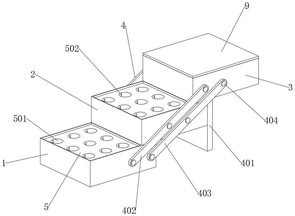
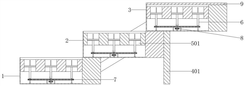
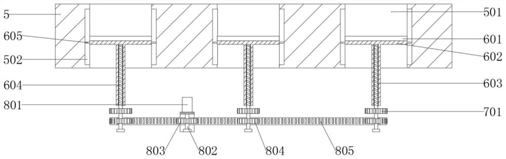
[0033] refer to Figure 1 to Figure 7, a kind of financial precious metal coin transshipment device of the present embodiment, comprises bottom box 1, middle box 2 and top box 3; The upper end is provided with a cover plate 9, and the left and right ends of the bottom box 1, middle box 2, and top box 3 are provided with an unfolding mechanism 4, and the inside of the bottom box 1, middle box 2, and top box 3 is fixed with a placement plate 5, and the lower end of the placement plate 5 is set There is a jacking mechanism 6, and the lower end of the jacking mechanism 6 is provided with a transmission mechanism 7 and a power mechanism 8. Specifically, the transmission mechanism 7 includes a transmission gear 701 and a transmission chain 702, and the lower end of the screw rod 604 is fixedly connected with a transmission gear 701. The outside of the transmission gear 701 is meshed with a transmission chain 702 .

[0034] Specifically, refer to Figure 1 to Figure 6 , the jacking...

Embodiment 2

[0042] Such as Figure 1 to Figure 8 As shown, the components that are the same as or corresponding to those in the first embodiment are marked with the corresponding reference numerals in the first embodiment. For the sake of simplicity, only the differences from the first embodiment will be described below. The difference between this embodiment two and embodiment one is: as Figure 8 As shown, the top box 3 and the front and rear sides of the right end of the cover plate 9 are provided with a rotating mechanism 10. The rotating mechanism 10 includes a lower fixed block 1001, a lug 1002, a rotating rod 1003, a rotating sleeve 1004 and an upper fixed block 1005. The front and rear sides are screwed with a lower fixing block 1001, the upper end of the lower fixing block 1001 is fixedly connected with lugs 1002 on the front and rear sides, and a rotating rod 1003 is fixedly connected between the front and rear side supporting ears 1002, and a rotating sleeve 1004 is set on the ...

Embodiment 3

[0045] Such as Figure 1 to Figure 7 with Figure 9 As shown, the components that are the same as or corresponding to those in the first embodiment are marked with the corresponding reference numerals in the first embodiment. For the sake of simplicity, only the differences from the first embodiment will be described below. The difference between this embodiment two and embodiment one is: as Figure 9 As shown, the top box 3 and the front and rear sides of the left end of the cover plate 9 are provided with a locking mechanism 11. The locking mechanism 11 includes an upper locking block 1101, a lower locking block 1102, a locking bar 1103 and a locking bolt 1104. Both sides are fixedly connected with an upper lock block 1101, and the front and rear sides of the left end of the top box 3 are fixedly connected with a lower lock block 1102, and both the upper lock block 1101 and the lower lock block 1102 are provided with lock holes, and the lock rod 1103 passes through the lock...


PUM


Abstract

The invention relates to the technical field of coin transfer devices for finance, in particular to a precious metal coin transfer device for finance. The precious metal coin transfer device comprisesa bottom box, a middle box and a top box; the middle box is arranged at the upper end of the bottom box, the top box is arranged at the upper end of the middle box, a cover plate is arranged at the upper end of the top box, unfolding mechanisms are arranged at the left ends and the right ends of the bottom box, the middle box and the top box, placing plates are fixedly connected into the bottom box, the middle box and the top box, jack-up mechanisms are arranged at the lower ends of the placing plates, and transmission mechanisms and power mechanisms are arranged at the lower ends of the jack-up mechanisms. Precious metal coins are stored in a coin storage cavity, and use is simple and convenient, the jack-up mechanisms drive the precious metal coins to move up and down in the coin storage cavity to facilitate putting in and taking out of the precious metal coins so as to prevent the precious metal coins from being damaged, the unfolding mechanisms can effectively unfold and fold thebottom box, middle box and top box, collection and inspection of the precious metal coins are facilitated, and the situation that the precious metal coins are damaged due to separating and falling ofthe bottom box, middle box and top box are effectively avoided.

Description

technical field [0001] The invention relates to the technical field of financial coin transfer devices, in particular to a financial precious metal coin transfer device. Background technique [0002] Finance (Finance, Finounce) is an economic activity in which market entities use financial instruments to transfer funds from the side with surplus funds to the side with scarce funds. Finance is the general term for monetary and capital integration. Mainly refers to various activities related to currency circulation and bank credit. The main contents include: issuance, release, circulation and withdrawal of currency; absorption and withdrawal of various deposits; issuance and recovery of various loans; bank accounting, cashier, transfer, settlement, insurance, investment, trust, lease, exchange, discount , Mortgage, securities trading and international trade and non-trade settlement, gold and silver trading, export, import, etc. [0003] Precious metal coins are national leg...

Claims


Application Information

Patent Timeline
IPC IPC(8): B65D25/02B65D25/52B65D21/032B65D55/02B65D25/20B65D81/02
CPCB65D21/0209B65D25/02B65D25/20B65D25/52B65D55/02B65D81/02
Inventor 王福礼窦丽荣王得旭
Owner 山东外国语职业技术大学
Why Eureka
Try Eureka