
Future urban rail system

A rail and urban technology, applied in the field of rail systems, can solve problems such as waste of space and energy, waste of commuting time, and low number of subway passengers

Inactive Publication Date: 2020-09-11
杨鸿苍 +2
View PDF5 Cites 0 Cited by
  • Summary
  • Abstract
  • Description
  • Claims
  • Application Information

AI Technical Summary

Problems solved by technology

The existing traffic is mainly transported by asphalt roads or subways. During peak hours in the morning and evening, there are almost one car and one person on the road. The number of people in the subway during non-commuting hours is relatively low, which is a serious waste of space and energy.
Moreover, the posture car must concentrate and hold the steering wheel with both hands. Commuting time is a waste of people's precious energy

Method used


Image

  • Future urban rail system
  • Future urban rail system
  • Future urban rail system

Examples


Embodiment Construction

[0044] In order to make the purpose, technical solutions and advantages of the embodiments of the present invention clearer, the technical solutions in the embodiments of the present invention will be clearly and completely described below in conjunction with the drawings in the embodiments of the present invention. Obviously, the described embodiments It is a part of embodiments of the present invention, but not all embodiments. The components of the embodiments of the invention generally described and illustrated in the figures herein can be arranged and designed in a variety of different configurations.

[0045] Accordingly, the following detailed description of the embodiments of the invention provided in the accompanying drawings is not intended to limit the scope of the claimed invention, but merely represents selected embodiments of the invention. Based on the embodiments of the present invention, all other embodiments obtained by persons of ordinary skill in the art wi...


PUM


Abstract

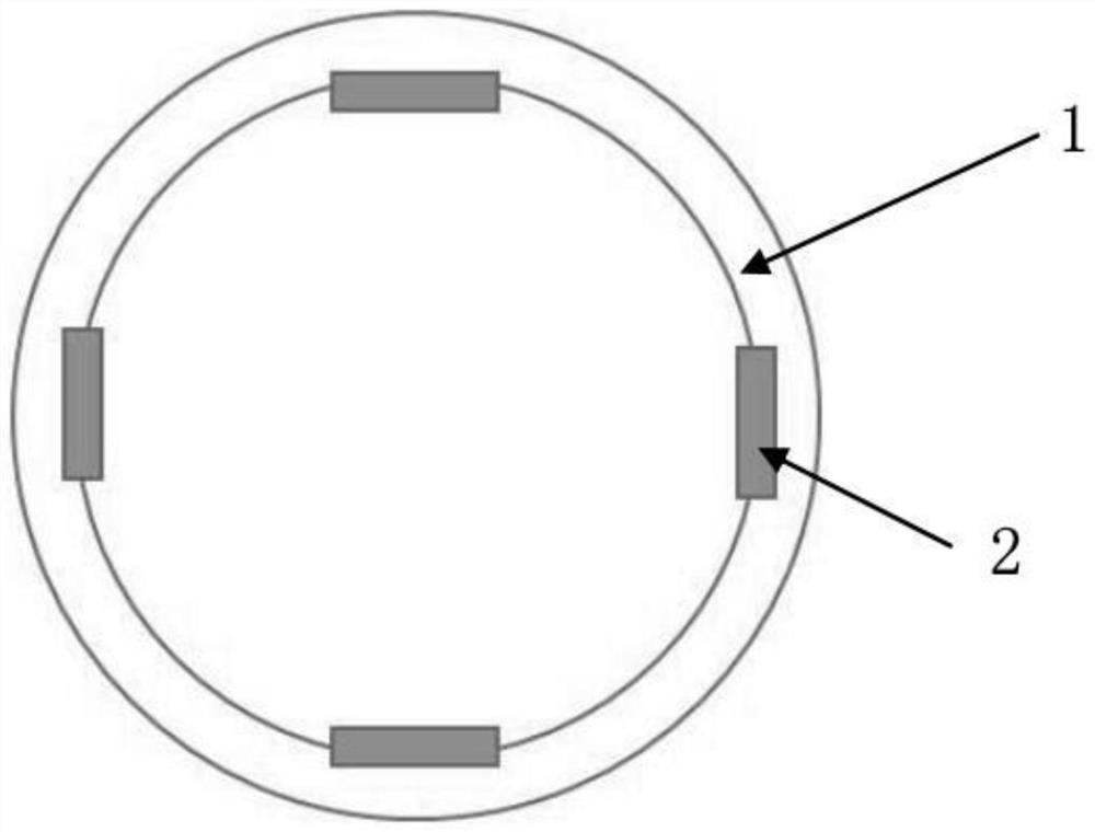
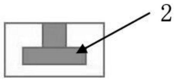
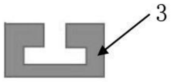
The invention provides a future urban rail system. The future urban rail system comprises a conveying pipeline, a rail transit transportation carrier and an operation control system. Four rails are arranged in the conveying pipeline; four groups of rail sliding devices corresponding to the four rails are respectively arranged outside the vehicle body of the rail transit transportation carrier; thefour rails are respectively a ground rail, a left rail, a right rail and an upper rail; the four groups of rail sliding devices are respectively a ground rail sliding device, a left side rail slidingdevice, a right side rail sliding device and an upper side rail sliding device; each set of rail sliding devices is arranged outside the corresponding rail in a sleeving mode and moves front and back. Unmanned driving, intelligent operation and efficient direct arrival are achieved, most urban taxis and private cars can be replaced, air pollution is reduced, traffic burdens are relieved, the probability of traffic accidents is reduced, ground activities are not affected at all, space resources are saved, and the energy utilization rate is increased.

Description

technical field [0001] The invention relates to a rail system, in particular to a future urban rail system. Background technique [0002] The urban areas where we live and work now are facing the status quo of high commodity prices, high housing prices, centralized industrial efficiency and cost cores, high knowledge, high competition, high salaries, and agglomeration of young and strong manpower. The highly concentrated population requires more efficient related facilities. . The existing traffic is mainly transported by asphalt roads or subways. During peak hours in the morning and evening, there are almost one car and one person on the road. The number of people carried by the subway during non-commuting hours is relatively low, which seriously wastes space and energy. Moreover, the posture car must concentrate and hold the steering wheel with both hands. Commuting time is a waste of people's precious energy. Contents of the invention [0003] The technical problem to...

Claims


Application Information

Patent Timeline
IPC IPC(8): E01B25/00E04H14/00B61B13/10
CPCB61B13/10E01B25/00E04H14/00
Inventor 杨鸿苍
Owner 杨鸿苍
Learn More