Combined type end plate and prefabricated pile

A combined and prefabricated pile technology, which is applied in sheet pile walls, buildings, and foundation structure engineering, can solve the problems of loss of concrete precompression stress, small end face protection of square piles, and weak connection, etc., and achieve high connection strength , to ensure the effect of firmness

Pending Publication Date: 2020-09-11
上海辅延建筑科技有限公司
View PDF2 Cites 1 Cited by
  • Summary
  • Abstract
  • Description
  • Claims
  • Application Information

AI Technical Summary

Problems solved by technology

[0010] On the one hand, the above-mentioned structural design adopts the small end plate structure, which will still cause partial loss of the effective precompression stress of the concrete. At the same time, the area of ​​the square small end plate is smaller than the end surface cross-sectional area of ​​the square pile, so the protection for the end surface of the square pile is relatively small. , and the end plate connection between the two concrete piles generally needs to be welded, but in the above technical scheme, there is no welding rod reserved on the end plate, so welding cannot be done, so the connection between the two end plates can only be done in External welds are made at the gaps at the edges, which would result in a weak connection between the two concrete piles
[0011] In short, the above-mentioned technical solutions have failed to effectively reduce costs, protect concrete piles, and the connection between adjacent concrete piles is not firm.

Method used


Image

  • Combined type end plate and prefabricated pile
  • Combined type end plate and prefabricated pile
  • Combined type end plate and prefabricated pile

Examples


Embodiment Construction

[0033] The preferred embodiments of the present invention will be described below in conjunction with the accompanying drawings. It should be understood that the preferred embodiments described here are only used to illustrate and explain the present invention, and are not intended to limit the present invention.

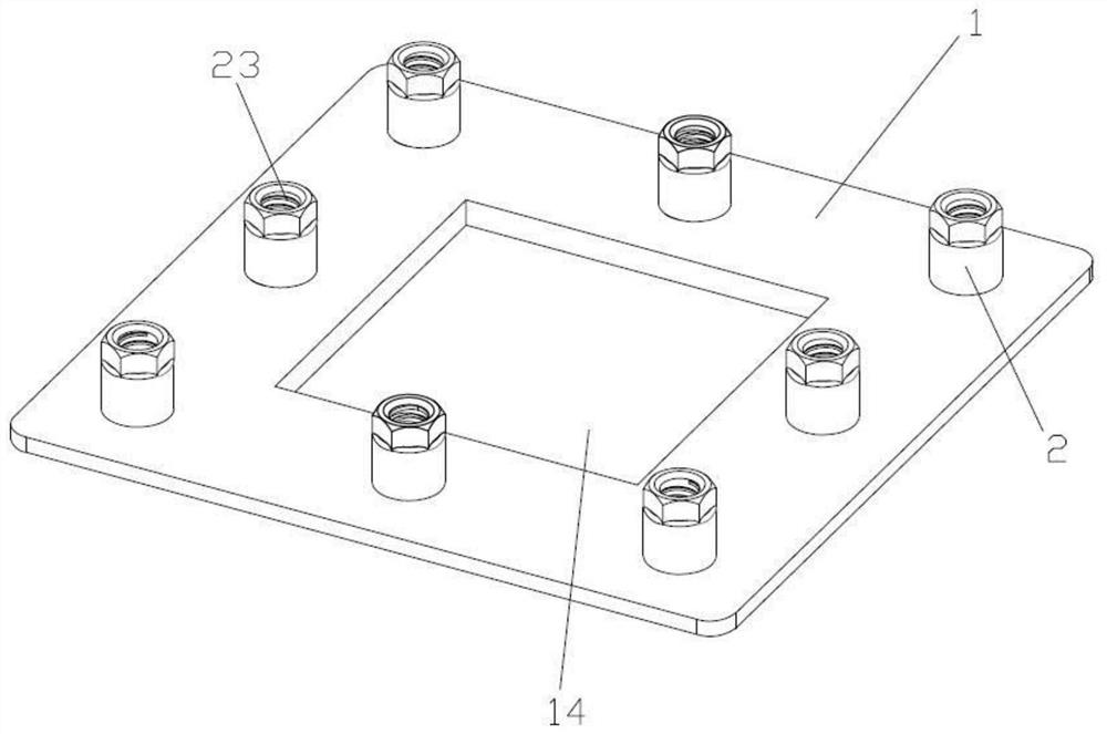
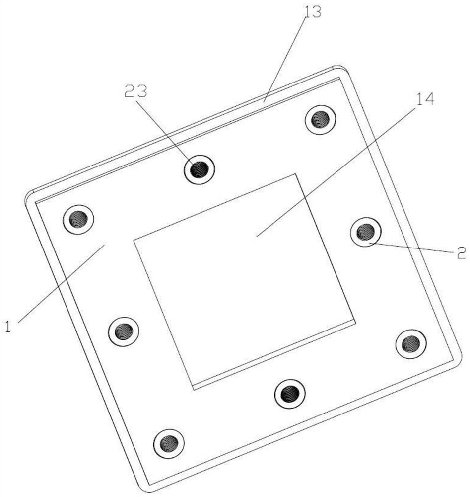
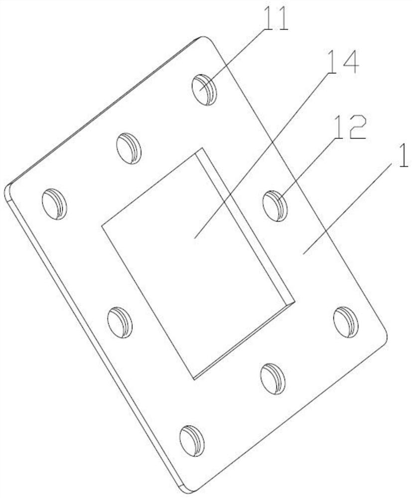
[0034] Such as Figures 1 to 4 As shown, a combined end plate includes an end plate 1, and the edge of the end plate 1 is provided with a plurality of evenly distributed mounting holes 11, and the mounting holes 11 are provided with internal threads 12, and also includes a plurality of connecting pieces 2 One, wherein the connector 2 can be a bolt, one end of each bolt 2 is provided with an external thread 21, and the bolt 2 is screwed with the internal thread 12 of the mounting hole 11 through the external thread 21, and the bolt 2 is provided with an anchor counterbore 22 and Internal thread 2 23, when installing, the steel bar heading of the PC prestressed main s...


PUM


Abstract

The invention relates to a combined type end plate and a prefabricated pile. End plate consumables can be effectively saved, the connecting firmness between a longitudinal main rib and the end plate of the prefabricated pile is guaranteed, and mounting is convenient. The combined type end plate comprises an end plate body. The combined type end plate is characterized in that multiple evenly-distributed mounting holes are formed in the end plate body, and internal threads or clamping grooves are formed in the mounting holes; and connecting parts are further included, external threads or bucklesare arranged on the connecting parts, the connecting parts are in screw joint with the internal threads or clamping grooves of the mounting holes through the external threads or buckles, connecting structures capable of being connected with the longitudinal main rib are arranged on the connecting parts, in the combined type end plate, tensioning force generated during prestress tensioning is nottransmitted through the end plate body through screw joint and clamped joint between the connecting parts internally provided with anchoring counterbores and the end plate body, finally, the tensioning force is borne by the connecting parts and the thread positions or clamped joint positions of connection of the connecting parts and the end plate body, then the end plate body can be effectively thinned, and the end plate body can be made to have the cross section the same as that of the concrete pile.

Description

technical field [0001] The invention relates to a combined end plate and a prefabricated pile. Background technique [0002] Concrete piles are piles made of concrete including ordinary reinforced concrete and prestressed concrete, which are often used in foundation construction projects. According to whether the two ends of the concrete pile include end plates, it can be divided into end sheet piles and endless sheet piles, wherein the two ends of the end sheet piles are respectively provided with end plates. [0003] At the beginning of the design of concrete piles, end-sheet piles are used. The reason why the end-sheet pile structure is adopted is that the connection between the two concrete piles can be welded through the end-plate to further ensure the firmness of the connection between the two concrete piles. On the other hand, the internal structure of the concrete pile is clamped by the anchor structure between the longitudinal steel bar and the end plate. The PC pr...

Claims


Application Information

Patent Timeline
Patent Type & Authority Applications(China)
IPC IPC(8): E02D5/30E02D5/58
CPCE02D5/30E02D5/58
Inventor 曹清清
Owner 上海辅延建筑科技有限公司
Why Eureka
Try Eureka