
Hospital temporary isolation house with ventilation structural design

A structural design and hospital technology, applied in hospitals, space heating and ventilation, building construction, etc., can solve the problems of temporary isolation house molding efficiency, insufficient number of partitions, slow molding cycle, etc., to facilitate installation and disassembly Effects of reusing, ensuring smooth internal air circulation, improving utilization rate and recycling rate

Inactive Publication Date: 2020-09-11
徐牛盅
View PDF11 Cites 3 Cited by
  • Summary
  • Abstract
  • Description
  • Claims
  • Application Information

AI Technical Summary

Problems solved by technology

[0003] However, when a strong infectious disease breaks out, it is usually accompanied by a large number of infected patients who get sick at the same time. This will easily lead to insufficient isolation materials in the hospital to meet the needs of patients. At this time, it is necessary to build a temporary isolation room. The existing temporary isolation room structure It is complex and the molding cycle is slow, which cannot meet the urgent treatment requirements of critically ill patients. At the same time, the existing temporary isolation room needs to be disinfected and isolated, resulting in poor internal ventilation conditions, which is not conducive to the recovery and treatment of patients, thus reducing the cure rate of patients. even worse
[0004] To this end, a hospital temporary isolation house with a ventilation structure design is provided to solve the molding efficiency and ventilation problems of the temporary isolation house

Method used


Image

  • Hospital temporary isolation house with ventilation structural design
  • Hospital temporary isolation house with ventilation structural design
  • Hospital temporary isolation house with ventilation structural design

Examples

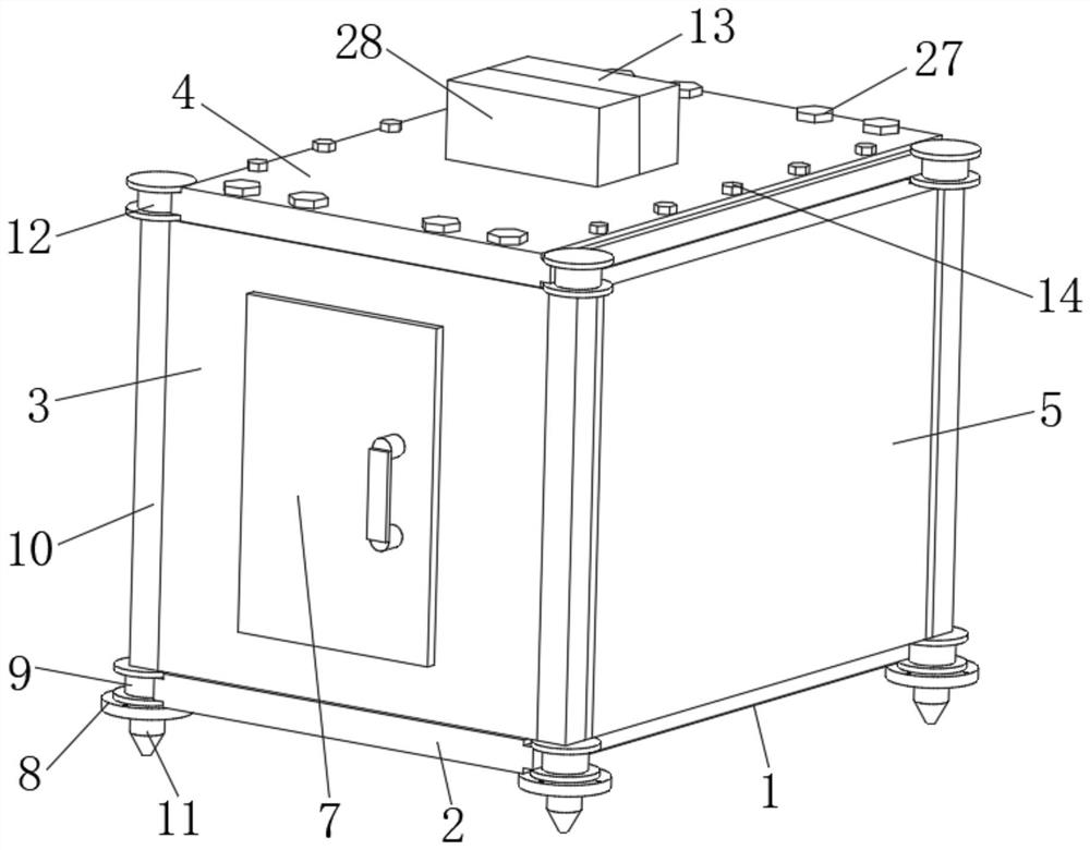
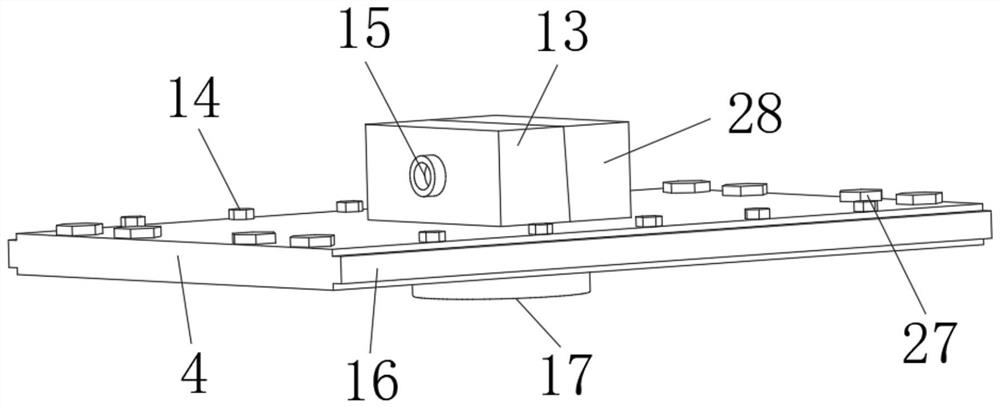
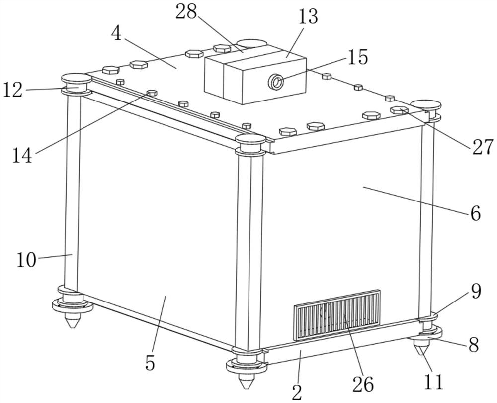

Embodiment Construction

[0025] The following will clearly and completely describe the technical solutions in the embodiments of the present invention with reference to the accompanying drawings in the embodiments of the present invention. Obviously, the described embodiments are only some, not all, embodiments of the present invention. Based on the embodiments of the present invention, all other embodiments obtained by persons of ordinary skill in the art without making creative efforts belong to the protection scope of the present invention.

[0026] see Figure 1 to Figure 6 , the present invention provides a technical solution:

[0027] A temporary hospital isolation house with a ventilation structure design, including a temporary isolation house 1, the temporary isolation house 1 is composed of a front panel 3, a rear panel 6, a bottom panel 2, a top panel 4 and a pair of left and right symmetrical side panels 5, the temporary The four corner positions of the isolation house 1 are all vertically...


PUM


Abstract

The invention relates to the technical field of medical temporary isolation houses, in particular to a hospital temporary isolation house with ventilation structural design. The house comprises a temporary isolation house body, the temporary isolation house body is composed of a front plate, a rear plate, a bottom plate, a top plate and a pair of side plates in bilateral symmetry, four corners ofthe temporary isolation house body are vertically provided with stand columns, and an inner cavity of the temporary isolation house body is arranged to be an isolation inner cavity. The house has thebeneficial effects that through cooperation between the stand columns and I-shaped wheels, the rapid and accurate installation on the side plates of the isolation house body is achieved, and meanwhile, through fixing of screws, the connection among the plate pieces of the isolation house is achieved, and the forming period is greatly shortened; and an air inlet fan and an air outlet fan are arranged in the isolation room body, so that the circulation ventilation is conducted on the isolation inner cavity, the smooth distribution of internal air is guaranteed, and great help is brought to recovery of a patient, and meanwhile, the humidity of the internal air is adjusted through a humidifier, the disinfection is conducted on exhausted air through a disinfection box and a filter box, and thevirus transmission infection is prevented.

Description

technical field [0001] The invention relates to the technical field of medical temporary isolation houses, in particular to a hospital temporary isolation house with ventilation structure design. Background technique [0002] During the treatment of a highly contagious disease, the patient needs to be isolated to prevent large-scale infection. At this time, the patient needs to be placed in an isolation room. [0003] However, when a strong infectious disease breaks out, it is usually accompanied by a large number of infected patients who get sick at the same time. This will easily lead to insufficient isolation materials in the hospital to meet the needs of patients. At this time, it is necessary to build a temporary isolation room. The existing temporary isolation room structure It is complex and the molding cycle is slow, which cannot meet the urgent treatment requirements of critically ill patients. At the same time, the existing temporary isolation room needs to be disi...

Claims


Application Information

Patent Timeline
IPC IPC(8): E04H1/12E04B1/343E04H3/08F24F3/16F24F6/00
CPCE04B1/34321E04H1/12E04H3/08F24F3/16F24F6/00Y02A50/20
Inventor 不公告发明人
Owner 徐牛盅
Learn More