Axial flow type jet fan
A technology of jet flow fan and axial flow fan, applied in axial flow pumps, mechanical equipment, non-variable pumps, etc., can solve the problems of unsatisfactory fire extinguishing effect and low working efficiency of fire extinguishing fans, and achieve light weight, simple structure, The effect of high work efficiency
- Summary
- Abstract
- Description
- Claims
- Application Information
AI Technical Summary
Problems solved by technology
Method used
Image

Examples
Embodiment
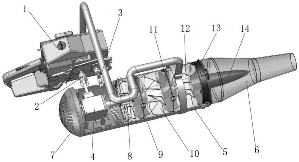
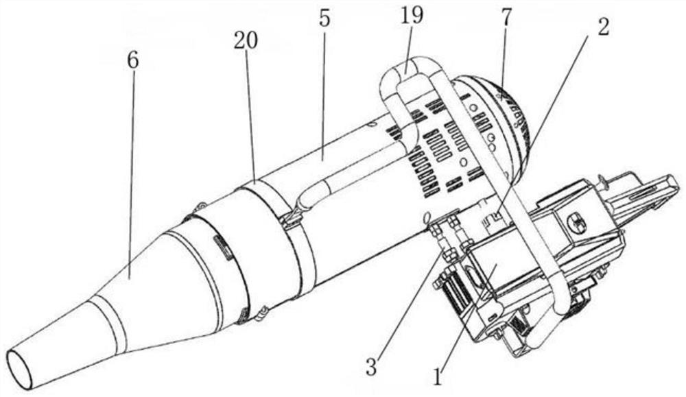
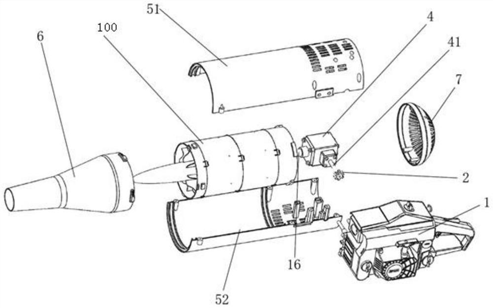
[0033] combine Figure 1-Figure 5 As shown, this embodiment provides an axial flow jet fan, including a small power source, a casing 5, a conical fan cylinder 6, a gear box, and a two-stage axial flow fan assembly 100;
[0034] The small-sized power source is arranged on the outside of the casing 5, the gear box is installed at the air inlet of the casing 5, and the input shaft of the gear box is connected to the small-sized power source through transmission;
[0035] The conical air cylinder 6 is installed at the air outlet of the housing 5, and the conical air cylinder 6 is provided with a diversion cone, and the diversion cone and the two-stage axial flow fan assembly 100 connect;
[0036] The two-stage axial flow fan assembly is arranged inside the casing 5, and the two-stage axial flow fan assembly includes an inlet rectifying grid 8 and a first moving impeller 9 sequentially installed on the output shaft of the gear box. , the first guide vane 10 , the second moving im...
PUM
 Abstract
Description
Claims
Application Information
 - R&D
- Intellectual Property
- Life Sciences
- Materials
- Tech Scout
- Unparalleled Data Quality
- Higher Quality Content
- 60% Fewer Hallucinations
Browse by: Latest US Patents, China's latest patents, Technical Efficacy Thesaurus, Application Domain, Technology Topic, Popular Technical Reports.
© 2025 PatSnap. All rights reserved.Legal|Privacy policy|Modern Slavery Act Transparency Statement|Sitemap|About US| Contact US: help@patsnap.com