
Track spoofing method based on GPS navigation

A GPS navigation and trajectory technology, applied in the GPS field, can solve the problems of interference, trajectory deception, and inability to accept communication control signals, i.e. remote control signals, etc.

Active Publication Date: 2020-09-11
UNIV OF ELECTRONICS SCI & TECH OF CHINA
View PDF4 Cites 9 Cited by
  • Summary
  • Abstract
  • Description
  • Claims
  • Application Information

AI Technical Summary

Problems solved by technology

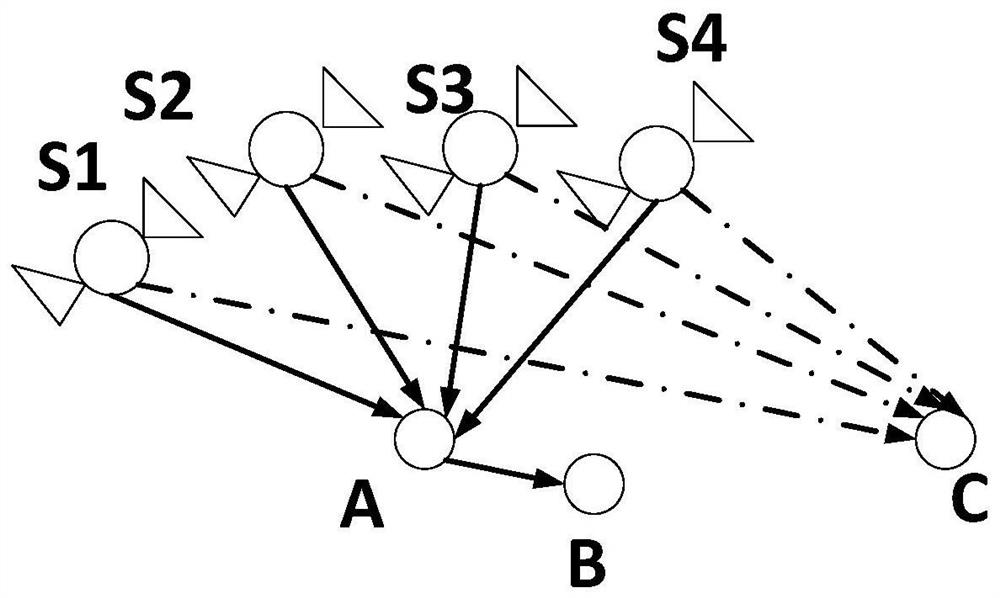
[0003] For the integrated navigation method combining GPS and inertial navigation (INS), the more common method is the loose coupling method. In the area to be protected, the UAV is continuously transmitting high-power interference RF signals to the target UAV, so that the UAV is in the In the barrier of interfering signals, the communication control signal, that is, the remote control signal, cannot be accepted, thus forcing the UAV to enter the automatic landing, automatic return or automatic navigation stage. If it enters the automatic navigation stage, the UAV can still pass through the preset route or The position coordinate information continues to move towards the intended target point, so further navigation interference measures are required, that is, trajectory deception
[0004] However, if the spoofing position and velocity (GPS spoofing trajectory) given by the GPS spoofing signal differ too much from the preset trajectory of the UAV, it will be discovered by the UAV, which cannot satisfy the concealment of spoofing

Method used


Image

  • Track spoofing method based on GPS navigation
  • Track spoofing method based on GPS navigation
  • Track spoofing method based on GPS navigation

Examples


Embodiment Construction

[0039]Specific embodiments of the present invention will be described below in conjunction with the accompanying drawings, so that those skilled in the art can better understand the present invention. It should be noted that in the following description, when detailed descriptions of known functions and designs may dilute the main content of the present invention, these descriptions will be omitted here.

[0040] 1. The principle of forwarding deception interference

[0041] For spoofing interference, there are generally two types: forwarding type and generating type. Because most of the pseudo codes in military use are P codes or Y codes, the cycle is long and the structure is complicated, because it is not easy to crack and generate, while in civilian use, C / A codes are mostly used. Moreover, the short-period structure is simple and easy to generate. Therefore, in general, the forwarding interference does not need to demodulate satellite signals, know the signal structure an...


PUM


Abstract

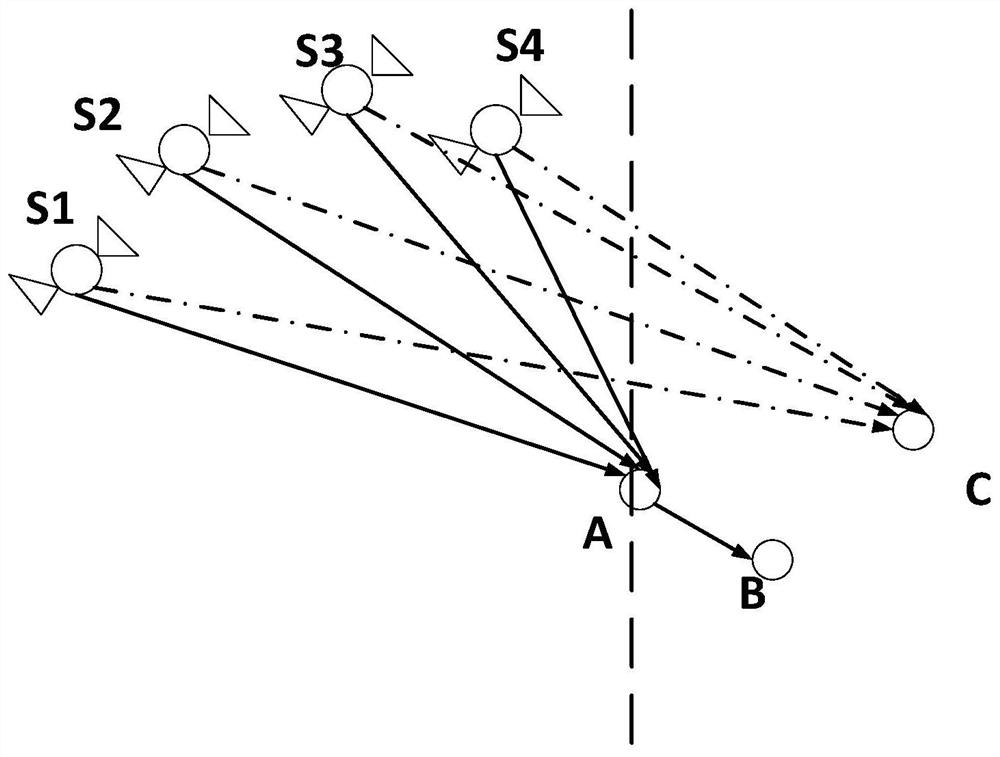
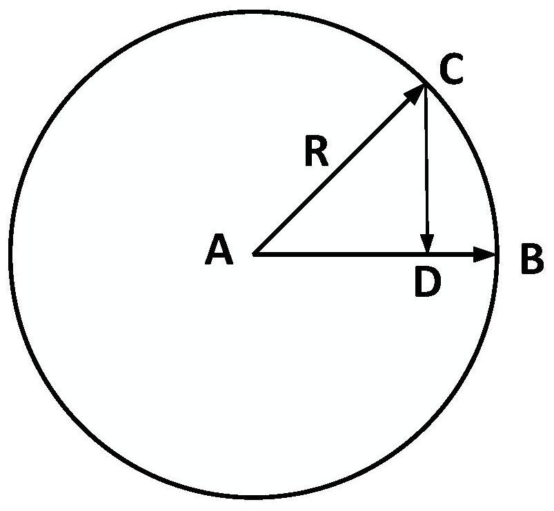
The invention discloses a track spoofing method based on GPS navigation, and the method comprises the steps: obtaining the real position and speed of an unmanned plane through a radar, calculating a preset track position according to the spoofing position and speed of a previous moment through a parallelogram rule, and carrying out the track fitting and extrapolation, and obtaining the preset track position of a next moment; and on the basis, constructing a vector A from the preset track position at the next moment to the real position at the moment of entering the interference airspace and avector B from the real position at the current moment to the real position at the moment of entering the interference airspace, performing offset direction judgment through an included angle, and performing offset to obtain a deception position at the moment Tn. Meanwhile, the vector C is constructed, and the offset rate is judged to be increased or decreased, so that the deviation between the deception speed at the current moment and the preset track of the unmanned aerial vehicle is small, the difference between the deception position and speed and the preset track of the unmanned aerial vehicle is small, the inertial navigation system of the unmanned aerial vehicle is deception, and the concealment requirement of deception is met.

Description

technical field [0001] The invention belongs to the technical field of GPS, and more specifically relates to a trajectory deception method based on GPS navigation. Background technique [0002] For this reason, anti-drone technology and trajectory deception technology based on GPS navigation are particularly important, and they have also begun to be gradually used in modern warfare. [0003] For the integrated navigation method combining GPS and inertial navigation (INS), the more common method is the loose coupling method. In the area to be protected, the UAV is continuously transmitted with high-power interference RF signals to the target UAV, so that the UAV is in the In the barrier of interfering signals, the communication control signal, that is, the remote control signal, cannot be accepted, thus forcing the UAV to enter the stage of automatic landing, automatic return or automatic navigation. If it enters the stage of automatic navigation, the UAV can still pass throu...

Claims


Application Information

Patent Timeline
Patent Type & Authority Applications(China)
IPC IPC(8): G01S19/39G01S19/47G01S19/21G01S19/01
CPCG01S19/393G01S19/47G01S19/015G01S19/215Y02T10/40
Inventor 韩尧李迪川张琦庞华吉李少华
Owner UNIV OF ELECTRONICS SCI & TECH OF CHINA
Learn More