Signal processing method and device, equipment and storage medium
A signal processing and displacement technology, applied in the field of communication, can solve the problems of inability to realize signal processing at the sending end or receiving end, low signal processing efficiency, etc.
- Summary
- Abstract
- Description
- Claims
- Application Information
AI Technical Summary
Problems solved by technology
Method used
Image

Examples
Embodiment 1
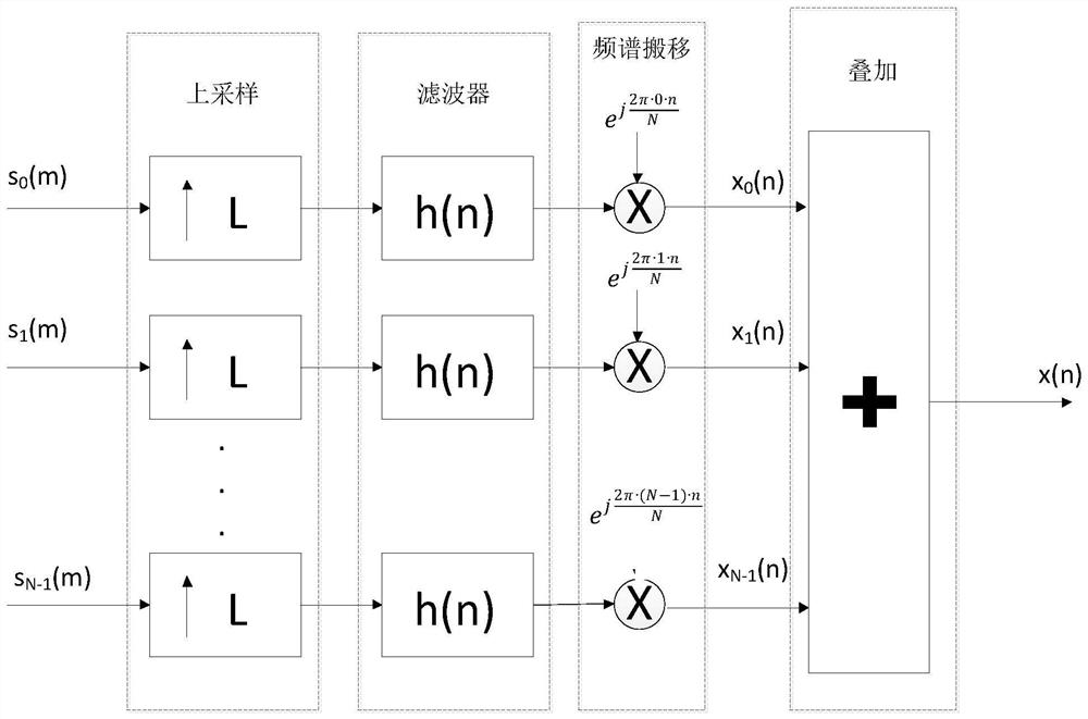
[0043] When the sending end is sending signals, its schematic diagram is as follows figure 1 shown. Suppose the sender has N channels, s i (m) represents the data in channel i at time m. Exemplary, s 0 (m) indicates the data in channel 0 at time m, s 1 (m) indicates the data in channel 1 at time m, s N-1 (m) represents data in channel N-1 at time m. Each channel is up-sampled separately, and then filtered using a low-pass filter h(n). After filtering, the frequency spectrum of each channel is shifted, and the sampled signal in channel i is according to Perform spectrum shifting, for example, channel 0 according to For spectrum shifting, channel 1 follows For spectrum shifting, channel N-1 follows Perform spectrum shifting, and after spectrum shifting, get the spectrum shifting result x i (m), for example, x i (m) represents the data in channel i at time m. Exemplary, x 0 (m) represents the spectrum shift result in channel 0 at time m, x 1 (m) represents the s...
Embodiment 2
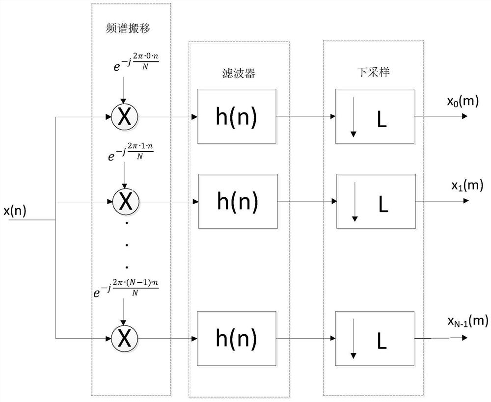
[0063] When the receiving end is receiving signals, its schematic diagram is as follows: image 3 shown. After the receiving end receives the signal x(n), according to the number of channels N in the N same channels according to Perform spectrum shifting. The sampled signal in channel i follows Perform spectrum shifting, for example, channel 0 according to For spectrum shifting, channel 1 follows For spectrum shifting, channel N-1 follows Perform spectrum shifting. Filter through the low-pass filter h(n), and then down-sample the filtered result to obtain the result data x i (m). Exemplary, x 0 (m) represents the result data in channel 0 at time m, x 1 (m) represents the result data in channel 1 at time m, x N-1 (m) represents the resulting data in channel N-1 at time m. At present, only the case where the downsampling multiple is equal to the number of channels is usually considered. If the sampling multiple is different from the number of channels, signal pro...
Embodiment 3
[0084] Figure 5 It is a schematic structural diagram of a signal processing device provided in Embodiment 3 of the present application. The device is applicable to a digital signal sending end, and the device may be located in a device that performs signal sending. The number of channels N at the sending end is K times the upsampling multiple L1, and K is an integer greater than or equal to 1. The device includes: a first inverse Fourier transform module 310, a first displacement module 320, a first filtering module 330, an upsampling module 340 and a delay adding module 350 .
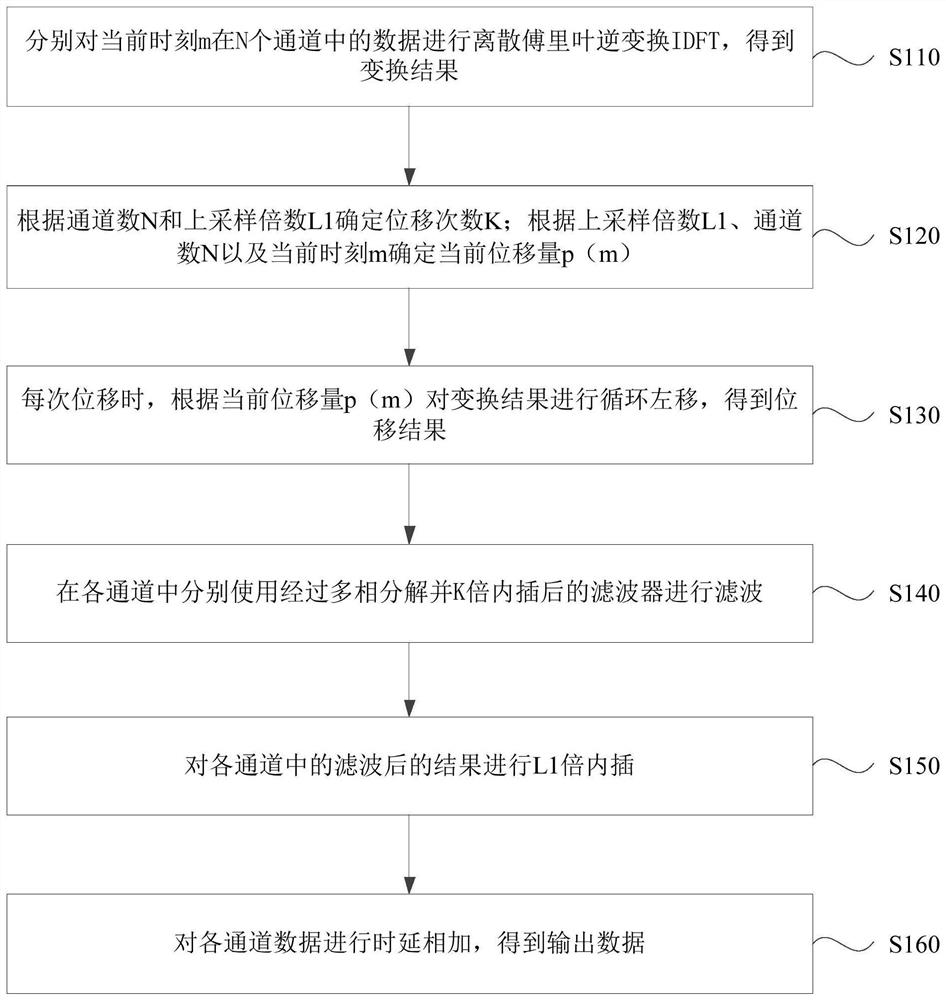
[0085] The first inverse Fourier transform module 310 is configured to perform discrete inverse Fourier transform (IDFT) on the data in the N channels at the current moment m to obtain a transform result.
[0086] The first displacement module 320 is used to determine the number of displacements K according to the number of channels N and the upsampling multiple L1; determine the current displacement...
PUM
 Abstract
Description
Claims
Application Information
 - R&D
- Intellectual Property
- Life Sciences
- Materials
- Tech Scout
- Unparalleled Data Quality
- Higher Quality Content
- 60% Fewer Hallucinations
Browse by: Latest US Patents, China's latest patents, Technical Efficacy Thesaurus, Application Domain, Technology Topic, Popular Technical Reports.
© 2025 PatSnap. All rights reserved.Legal|Privacy policy|Modern Slavery Act Transparency Statement|Sitemap|About US| Contact US: help@patsnap.com