
An FPGA implementation method of combined pulse compression and projectile velocity compensation for hypersonic platforms

A pulse compression, hypersonic technology, applied in radio wave measurement systems, instruments, etc., can solve the problems of high development cost, reduce signal processing efficiency, increase data interaction time, etc., to reduce the demand for hardware resources and improve signal processing. The effect of efficiency

Active Publication Date: 2021-01-19
SHANGHAI RADIO EQUIP RES INST
View PDF3 Cites 0 Cited by
  • Summary
  • Abstract
  • Description
  • Claims
  • Application Information

AI Technical Summary

Problems solved by technology

It has two disadvantages. One is that the pulse compression and projectile speed compensation processing are completed on different hardware platforms in a sequential cascading manner. The data interaction between different platforms increases a large amount of temporary data, which increases the data interaction time. , which reduces the signal processing efficiency and increases the memory requirements of the signal processor, which is contrary to the actual situation of the shortage of hardware resources and computing resources of the missile-borne platform; secondly, when the radar data volume is large, in order to achieve signal To deal with real-time requirements, radar usually adopts multi-channel multi-task processing technology, which is limited by the number of processors inside the DSP chip. The disadvantage of a single DSP chip is that the multi-channel multi-task processing capability is limited. Channel multi-tasking signal processing needs, but the development cost is high, which reduces the economic benefits of the product, and is not suitable for use on missile-borne platforms

Method used


Image

  • An FPGA implementation method of combined pulse compression and projectile velocity compensation for hypersonic platforms
  • An FPGA implementation method of combined pulse compression and projectile velocity compensation for hypersonic platforms
  • An FPGA implementation method of combined pulse compression and projectile velocity compensation for hypersonic platforms

Examples


Embodiment Construction

[0042] The present invention will be further elaborated below by describing a preferred specific embodiment in detail in conjunction with the accompanying drawings.

[0043] A kind of FPGA implementation method of hypersonic platform joint pulse compression and projectile velocity compensation of the present invention, it comprises the following steps:

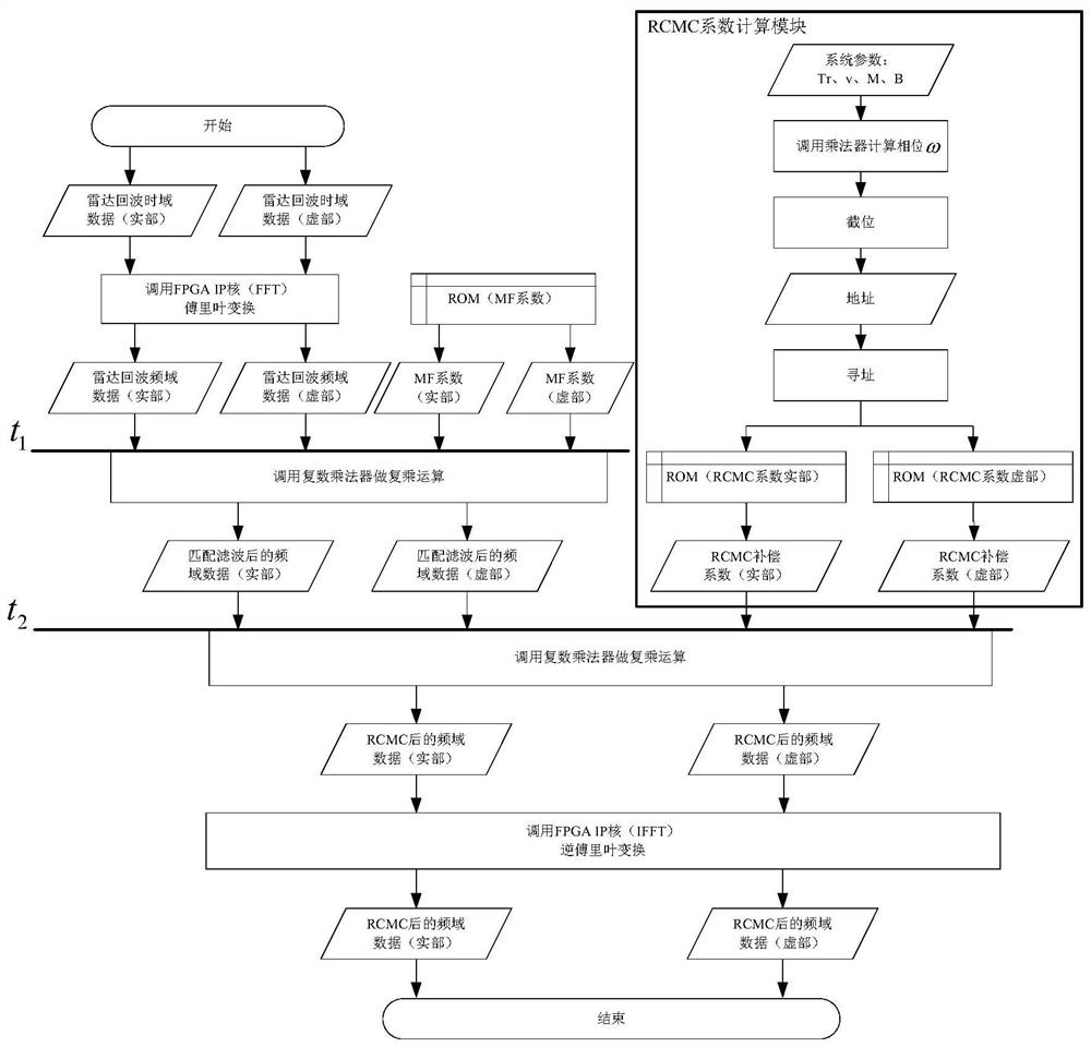
[0044]S1, using the carrier frequency f 0 , bandwidth B, pulse duration T p , chirp frequency k, pulse number M, projectile distance R 0 , These parameters calculate the real part and the imaginary part of the radar echo time domain data, and the real part and the imaginary part of the frequency domain matched filter coefficient. In the present embodiment, the radar echo data is generated in MATLAB , matched filter (MF) coefficient; the real part and the imaginary part of frequency domain matched filter coefficient are stored in two coe files respectively, and these two coe files are stored in two ROMs respectively;

[0045...


PUM


Abstract

The invention provides a FPGA implementation method of hypersonic velocity platform combined pulse compression and elastic speed compensation. The combined algorithm of the pulse compression and the elastic speed compensation is adopted in the FPGA, the requirement for a memory is reduced, the resource utilization rate is effectively improved, the data throughput of a missile-borne system is increased, and the multi-channel multi-task processing capability of the missile-borne platform is further improved as well; a missile-speed compensation algorithm is realized on the FPGA, under the background of the missile-borne big data processing application, the advantages of FPGA parallel processing improve the signal processing efficiency, the requirement for real-time performance of signal processing by the missile-borne platform is met, and the advantages that power consumption is low and the method is prone to be realized in a project are particularly suitable for being used on the missile-borne platform with limited power consumption resources.

Description

technical field [0001] The invention relates to the technical field of missile-borne radar, in particular to an FPGA implementation method for a hypersonic platform combined with pulse compression and bullet velocity compensation. Background technique [0002] Patent No. 201610218761.3 "A Sonar Signal Processing Method Based on ZYNQ-7000 Platform", this patent uses FPGA to implement modular processing for the MVDR direction finding algorithm in sonar signal processing, that is, put the modules on the platform separately Running in dual-core processors and FPGAs, it solves the shortcoming of insufficient logic units when only using FPGAs for processing. This method requires that the processing platform has a dual-core parallel processing capability, and has relatively high requirements on the hardware of the processing platform. [0003] Patent No. 201410310034.0 "An FPGA-Based Anti-Same-Channel Interference Signal Processing Method for Marine Radar", this patent implements ...

Claims


Application Information

Patent Timeline
Patent Type & Authority Patents(China)
IPC IPC(8): G01S7/52
CPCG01S7/52004
Inventor 施君南侯凯强许彦章张天健郭冬梅周郁邹波
Owner SHANGHAI RADIO EQUIP RES INST
Learn More