A control method for the heat dissipation system of a large-capacity generating set

A technology for generating sets and heat dissipation systems, which is applied in the direction of electric components, engine components, machines/engines, etc., can solve the problems of complex heat dissipation system structure, uneven temperature, large ventilation loss, etc., to achieve heat dissipation effect, reduce ventilation volume, The effect of reducing power consumption of the unit

Active Publication Date: 2021-04-06
浙江富春江水电设备股份有限公司
View PDF5 Cites 0 Cited by
  • Summary
  • Abstract
  • Description
  • Claims
  • Application Information

AI Technical Summary

Problems solved by technology

[0006] The purpose of the present invention is to provide a control method for the heat dissipation system of a large-capacity generating set in order to solve the problems of large ventilation loss, low efficiency, and uneven temperature in the existing water turbine generator heat dissipation system. Reduce ventilation loss, improve heat dissipation and cooling efficiency, ensure uniform heat dissipation of the generator set, and avoid complex structure of the heat dissipation system

Method used


Image

  • A control method for the heat dissipation system of a large-capacity generating set
  • A control method for the heat dissipation system of a large-capacity generating set
  • A control method for the heat dissipation system of a large-capacity generating set

Examples


Embodiment Construction

[0041] The present invention will be further described below in conjunction with the accompanying drawings and specific embodiments.

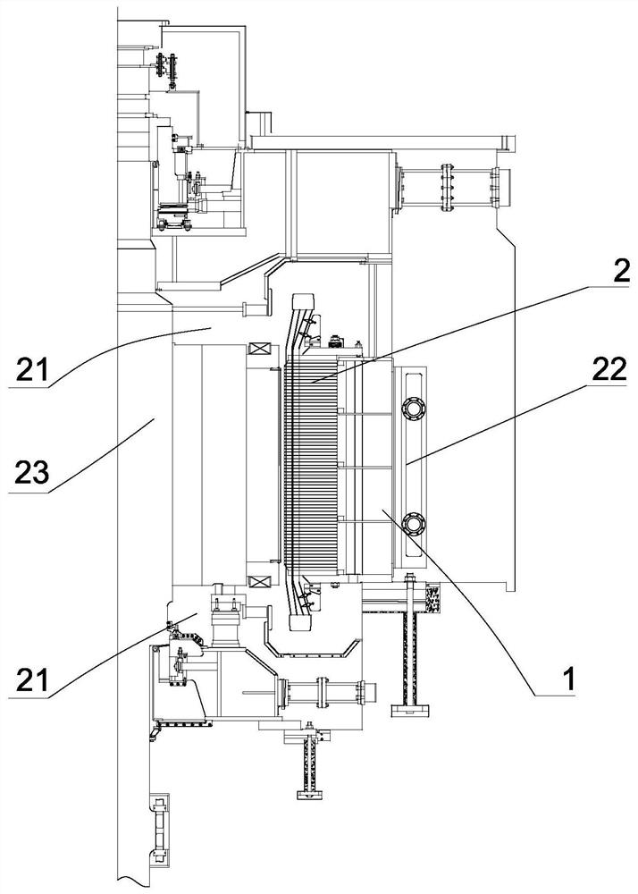
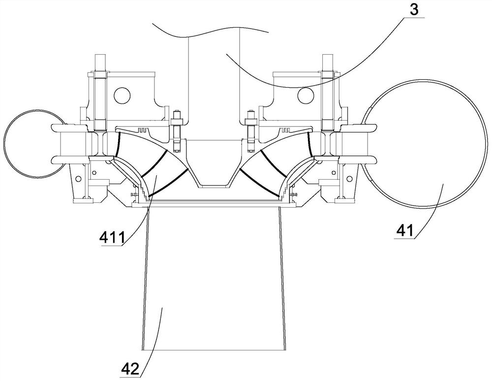
[0042] A control method for the heat dissipation system of a large-capacity generating set, such as figure 1 As shown, the generator set includes a stator 1, a rotor 2 rotatably arranged in the stator, and an air supply device (not shown in the figure) for driving cooling air to dissipate heat for the rotor and the stator, and the rotor is driven with the runner connect. The runner is rotatably set in the volute of the machine pit, such as figure 2 As shown, the runner includes a shaft body 3 connected with the rotor transmission, blades arranged on the shaft body, the volute is provided with a water inlet side and a water outlet side, the water inlet side is provided with a water inlet pipe 41, and the water outlet side of the volute is provided with a water outlet pipe 42. One end of the water inlet pipe is the water spray port 411 facing ...


PUM


Abstract

The invention discloses a method for controlling the heat dissipation system of a large-capacity generator set, which comprises the following steps: when the runner drives the rotor to rotate to generate electricity, the rotating shaft on the rotor drives the centrifugal fan blades to rotate, thereby inhaling the cold air at the air inlet end, and the cold air passes through The ventilation holes on the yoke radially flow out and spray onto the stator to absorb heat and become hot air, and then discharge out through the air outlet; detect the temperature difference ∆T between the air end and the air inlet end, and compare it with the set temperature difference δT For comparison; when ∆T≤0.95δT, reduce the friction between the shaft and the centrifugal fan blades to reduce the speed of the centrifugal fan blades; when ∆T≥1.05δT, increase the friction between the shaft and the centrifugal fan blades Force to increase the rotational speed of centrifugal fan blades, when 0.95δT<∆T<1.05δT, keep the above friction constant. The invention can significantly reduce the ventilation loss, improve the heat dissipation and cooling efficiency, ensure the uniform heat dissipation of the generating set, and avoid the complex structure of the heat dissipation system.

Description

technical field [0001] The invention relates to the technical field of hydroelectric generators, in particular to a control method for a heat dissipation system of a large-capacity generating set. Background technique [0002] With the enhancement of people's awareness of energy conservation and environmental protection, hydropower as a green energy is being vigorously developed. In the field of hydropower, the water turbine is a key part, which usually includes a stator, a rotor rotatably arranged in the stator, and a rotor for driving the rotor. Rotating runner, wherein the runner is set in a volute, and the volute is set in the machine pit. The runner includes several blades. One side is provided with a water inlet pipe with an opening aligned with the water-facing surface of the blade, and the other side of the volute is provided with a water outlet pipe. The rotor includes a rotor shaft connected to the rotor drive, a rotor yoke connected to the rotor shaft through a r...

Claims


Application Information

Patent Timeline
Patent Type & Authority Patents(China)
IPC IPC(8): H02K9/06H02K1/20H02K1/32H02K9/193F03B13/00
CPCF03B13/00F05B2220/706H02K1/20H02K1/32H02K9/06H02K9/193
Inventor 马建峰刘思靓刘胜柱
Owner 浙江富春江水电设备股份有限公司
Why Eureka
Try Eureka