Refrigeration equipment for data machine room

A technology of refrigeration equipment and data room, which is applied in the construction parts of electrical equipment, cooling/ventilation/heating transformation, electrical components, etc., which can solve the problems of inability to cool the unit, and achieve the effect of improving the cooling effect and improving the efficiency of heat dissipation and cooling

Inactive Publication Date: 2021-01-22
西安思明制冷设备工程有限公司
View PDF2 Cites 1 Cited by
  • Summary
  • Abstract
  • Description
  • Claims
  • Application Information

AI Technical Summary

Problems solved by technology

[0007] The purpose of the present invention is to solve the problem in the prior art that the units in each position inside the data room cannot be cooled sufficiently and quickly, and a kind of refrigeration equipment for the data room is proposed

Method used


Image

  • Refrigeration equipment for data machine room
  • Refrigeration equipment for data machine room
  • Refrigeration equipment for data machine room

Examples


Embodiment 1

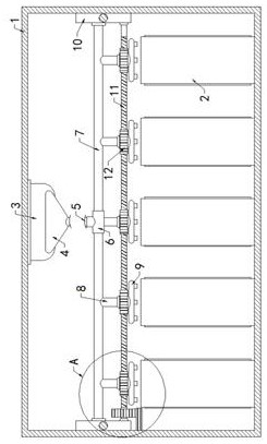
[0025] Example 1 as Figure 1-2 As shown, the refrigeration equipment used in the data computer room includes a computer room 1 and a plurality of units 2, and the plurality of units 2 are located inside the computer room 1. The top of the inner surface of the computer room 1 is fixed with an air conditioner 3, and the front side of the air conditioner 3 is fixedly installed. There is an air inlet pipe 4, the bottom of the air inlet pipe 4 is connected with a hose 5, the bottom of the hose 5 is connected with a three-way pipe 6, and both ends of the three-way pipe 6 are connected with an air guide pipe 7, and a three-way pipe is provided. 5. The two air guide tubes 7 are supported and connected. The bottoms of the tube walls of the two air guide tubes 7 are connected with a plurality of shunt pipes 8, and the pipe walls of the shunt pipes 8 are connected to the outlet pipe 9 through the first rotating bearing. 9 is located above the unit 2, and both ends of the two air ducts 7...

Embodiment 2

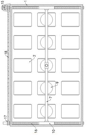
[0026] Embodiment 2 is on the basis of embodiment 1 such as Figure 2-3 As shown, its rotating mechanism includes a worm 11 and a plurality of worm wheels 12, the worm 11 is located at the rear side of the air outlet pipe 9, and both ends are rotatably connected with the two sliders 10 through the second rotating bearing, and the plurality of worm wheels 12 are respectively It is fixedly socketed with the pipe walls of a plurality of air outlet pipes 9, and the worm wheel 12 is engaged with the worm screw 11, and the worm wheel 11 can drive the worm wheel 12 to rotate.

Embodiment 3

[0027] Embodiment 3 is such as on the basis of embodiment 1 image 3 As shown, its transmission mechanism includes a gear 13 and a rack 14. The rack 14 is fixedly connected to the upper left end of the inner surface of the machine room 1 and is located below the slider 10. The fixed position of the gear 13 does not hinder the normal operation of the slider 10. Moving, the gear 13 is fixedly socketed with the left end of the worm 11 and meshed with the rack 14 .


PUM


Abstract

The invention relates to the technical field of refrigeration equipment, and discloses refrigeration equipment for a data machine room. Therefrigeration equipment comprises a machine room and a plurality of units, the plurality of units are all located in the machine room, an air conditioner is fixedly arranged at the top of the inner surface of the machine room, an air inlet pipe is fixedly arranged at the front side of the air conditioner, the bottom of the air inlet pipe is communicated with a hose, and a three-way pipe is communicated with the bottom of the hose, the two ends of the three-way pipe are communicated with air guide pipes correspondingly, the bottoms of the pipe walls of the two air guide pipes are communicated with a plurality of flow dividing pipes correspondingly, the pipe walls of the flow dividing pipes are rotationally connected with air outlet pipes through first rotating bearings, the air outlet pipes are located above the units, sliding blocks are fixedly arranged at both ends of the two air guide pipes correspondingly, and reciprocating moving mechanisms are arranged in the two sliding blocks. A rotating mechanism is arranged between the two sliding blocks and located below the air guide pipes, and a transmission mechanism is arranged at the upper end of the inner surface of the machine room. According to the invention, the units at all positions in the data machine room can be fully and rapidly cooled.

Description

technical field [0001] The invention relates to the technical field of refrigeration equipment, in particular to a refrigeration equipment for a data machine room. Background technique [0002] The data computer room is a construction site that provides an operating environment for centralized electronic information equipment. The numerous units in the existing data computer room will generate a lot of heat when they are working. Therefore, cooling equipment such as air conditioners is required to cool the inside of the computer room. [0003] Among them, the patent No. CN206771602U discloses a precision air-conditioning system for a data computer room, which includes a floor, a cabinet, an air-conditioning main unit and an air duct. There are inclined air outlets on the floor, and the floor is overhead and installed in the computer room. , the cabinet and the air conditioner host are placed on the floor, and the air duct is erected on the top of the machine room to connect ...

Claims


Application Information

Patent Timeline
Patent Type & Authority Applications(China)
IPC IPC(8): H05K7/20
CPCH05K7/20745
Inventor 王凯
Owner 西安思明制冷设备工程有限公司
Why Eureka
Try Eureka