Firebox for grill

A combustion chamber and grate technology, which is applied in the field of combustion chambers of ovens, can solve the problems of ceramic combustion chambers that are easy to break

Active Publication Date: 2020-09-11
家用取暖器公司D B A 安全烤炉
View PDF15 Cites 1 Cited by
  • Summary
  • Abstract
  • Description
  • Claims
  • Application Information

AI Technical Summary

Problems solved by technology

[0014] Also, for manufacturers of ovens and fireboxes, another issue concerns the shipping of one-piece design ceramic fireboxes, new or as replacements to fulfill their warranties
This is due to the brittleness of the ceramic material, and the ceramic combustion chamber is easily broken during transportation

Method used


Image

  • Firebox for grill
  • Firebox for grill
  • Firebox for grill

Examples


Embodiment Construction

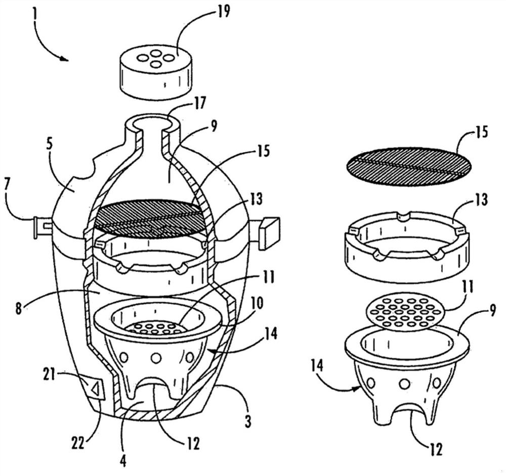
[0061] Figure 1 shows an example of an oven 1 known in the art. The oven 1 has a main body 3 and a cover 5 . The lid 5 can be opened and closed on the main body 3 using the handle 7 .

[0062] The oven 1 comprises a lower interior cavity 8 defined by a body 3 and an upper interior cavity 9 defined by a cover 5 .

[0063] At the bottom of the lower cavity 8 of the body 3 is the bottom wall 4 . The one-piece designed ceramic combustion chamber 10 is inserted into the lower inner cavity 8 of the main body 3 and rests on the bottom wall 4 . The combustion chamber 10 holds a grate 11 which in turn will hold combustion material, such as blocks. A fire ring 13 is placed adjacent to the combustion chamber 10 and holds a grill grate 15 on which food cooked by the oven 1 is placed.

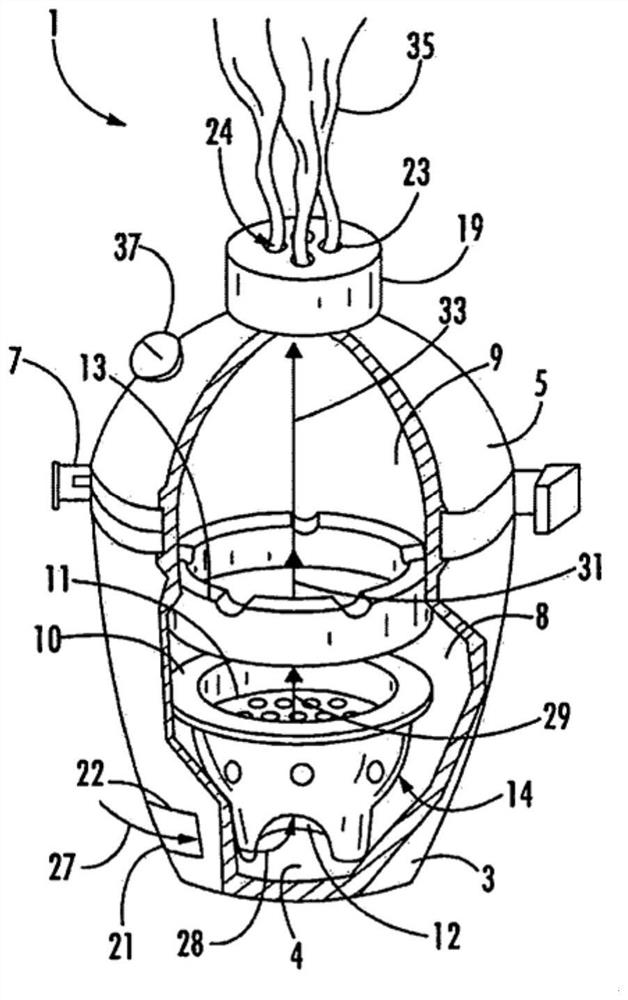
[0064] As shown in FIG. 1 , the main body 3 of the oven 1 has a vent door 21 movable from a fully closed position shown in FIG. 1 to a fully open position shown in FIG. 2 . The opening provided by the ...


PUM


Abstract

A firebox for a grill is provided. The firebox has a shell, an insulation layer, and a firebrick layer. The firebrick layer comprising a plurality of firebricks that form an inner peripheral surface of the firebox. The insulation layer formed between the firebrick layer and the shell or the insulation layer forming the outermost layer of the firebox. The shell preventing the collapse and / or unwanted airflow into the internal cavity of the firebox if a fracture is formed in the firebrick layer.

Description

technical field [0001] The present invention relates generally to ovens for cooking, and more particularly to a combustion chamber for an oven. Background technique [0002] Many modern ovens have a one-piece ceramic designed combustion chamber. The use of ceramics in combustion chambers has many advantages compared to other materials, the main being excellent thermal insulation. [0003] The ceramic burners retain heat for a long time as they can be used for grilling, smoking and roasting, making them very versatile. This allows the oven to have a constant temperature as low as 225°F and as high as 750°+F. [0004] Plus, using the ventilation system typical in an oven, precise control over airflow is maintained, allowing the oven to function more like a wood-burning oven and can be used for smoking, roasting, or roasting anything. [0005] However, modern ovens are not without their drawbacks. For example, a major problem faced by oven and combustion chamber manufacture...

Claims


Application Information

Patent Timeline
Patent Type & Authority Applications(China)
IPC IPC(8): A47J37/07A47J37/06
CPCA47J37/0704A47J37/0759A47J37/0786
Inventor 斯蒂芬·本森雅龙·本森
Owner 家用取暖器公司D B A 安全烤炉
Why Eureka
Try Eureka