Pressure-reduction insole structure

A technology of insole and thin pad is applied in the field of decompression insole structure, which can solve the problems of upper and lower dislocation, hindering the settlement of the sole of the foot, increasing the chance of sprains, etc., and achieves the effects of decompression in sports, easy and smooth movement, and strong stability.

Active Publication Date: 2020-09-15
涂旭东
View PDF7 Cites 3 Cited by
  • Summary
  • Abstract
  • Description
  • Claims
  • Application Information

AI Technical Summary

Problems solved by technology

[0004] For a pair of sports shoes with good performance, the tread angle and curve of the bottom of the sneakers are the key factors, but the design of general sneakers ignores this extremely important key, although some sneakers with forefoot air cushion and thick sole insole can be compressed by these materials characteristics, to obtain the required subsidence of the soles of the feet, but the physical phenomenon that the tread of the insole and the bottom of the insole are dislocated up and down during lateral movement, causing the soles of the feet to easily turn outwards
In addition, the high-thickness insole 5 is an extra point in terms of the shock-absorbing function, but if it is to obtain a suitable force angle on the ground, the high-thickness insole 5 will be resistance, hindering the most appropriate settlement of the sole of the foot, because the insole 5. After lateral dislocation, when the bottom arc with high inner side is stopped or changed direction laterally, the sole surface of the shoe is higher from the ground, and the inner side of the sole is raised higher to cause valgus (such as Figure 11 As shown), not only is it difficult to maintain a stable body movement, but the outside of the ankle must also increase force to balance, and increasing the burden of muscle strength will also increase the chance of sprain, and the sole of the foot will slide to the outside and it is difficult to support

Method used


Image

  • Pressure-reduction insole structure
  • Pressure-reduction insole structure
  • Pressure-reduction insole structure

Examples


Embodiment Construction

[0050] In order to have a clearer understanding of the technical solutions, objectives and effects of the present invention, the specific implementation manners of the present invention will now be described with reference to the accompanying drawings.

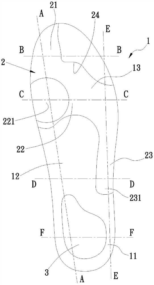
[0051] First, see figure 1 As shown, it is a schematic diagram of the three-dimensional appearance of the decompression insole structure of the present invention, including:

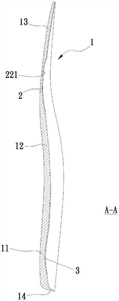
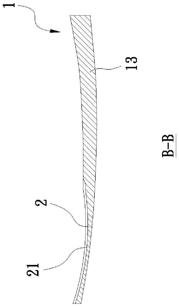
[0052] An insole body 1, the insole body 1 includes a heel area 11, an arch area 12, and a forefoot area 13 that gradually become thinner from thicker, and the forefoot area 13 is tilted upwards, on the insole body 1 A guiding thin pad 2 is provided between the forefoot area 13 and the arch area 12, and a rear stabilizing thin pad 3 is provided in the heel area 11, wherein:

[0053] The guide thin pad part 2 includes a thumb segment 21 corresponding to the first phalanx a1 of the human foot, a thumb segment 21 connected to the thumb segment 21 and corres...


PUM


Abstract

The invention relates to a pressure-reduction insole structure. The pressure-reduction insole structure comprises an insole body, wherein a guide thin pad part and a rear stable thin pad part are arranged on the insole body; wherein the guide thin pad part is used for accommodating areas from a metatarsophalangeal joint where a first phalanx of a forefoot is connected with a first metatarsophalanx(metatarsophalanx) to a metatarsophalangeal joint where a fifth phalanx is connected with a fifth metatarsophalanx (metatarsophalanx), and the rear stable thin pad part is used for accommodating a heel bone and enabling the first metatarsophalangeal joint to be at the lowest point of a treading position; therefore, a good walking dynamic environment is provided for the feet, enough space is provided, the thickness can be decreased progressively on the movement path of the feet to guide and complete a dynamic step, the standing stability is improved, and the effect of relieving the pressure ofthe feet can be achieved no matter whether a wearer is in a dynamic state or a static state.

Description

technical field [0001] The invention relates to a decompression insole structure, especially an insole structure conforming to the movement state (dynamic or static) of human feet, which can smoothly guide stress dispersion and reduce foot pressure. Background technique [0002] Now most of the original insoles attached to the shoes are flat insoles with equal thickness. Some may have a little more arch thickness to increase support. If the shoe is a high unit price, the arch may be installed. Stabilize the hard block; then, add cushioning rubber blocks to the place where the foot pressure is the greatest, that is, the heel and forefoot to reduce the impact from the ground, but the cushioning rubber blocks instead form resistance during travel, waste kinetic energy, and increase travel time. exerted force. [0003] The following describes the normal gait process in three steps: see Figure 10 As shown, in step (1) in the figure, the pedal position is in front of the body an...

Claims


Application Information

Patent Timeline
Patent Type & Authority Applications(China)
IPC IPC(8): A43B17/00
CPCA43B17/00
Inventor 涂旭东
Owner 涂旭东
Why Eureka
Try Eureka