Gas injection type rotary detonation ramjet combustion chamber

A technology of ramjet engine and combustion chamber, which is applied in the direction of ramjet engine, deflagration combustion chamber, combustion chamber, etc. It can solve the problems of low engine thrust performance, insufficient engine ramming effect, and inconspicuous air pressurization, etc., to achieve improved mixing effect, improving combustion efficiency, and expanding the range of the flight envelope

Active Publication Date: 2020-09-15
NAT UNIV OF DEFENSE TECH
View PDF4 Cites 13 Cited by
  • Summary
  • Abstract
  • Description
  • Claims
  • Application Information

AI Technical Summary

Problems solved by technology

Conventional rotary detonation engines rely solely on the effect of air ramming, so when the flight speed is low, the engine ramming effect is not enough, the air boost is not obvious, and the engine thrust performance is low

Method used


Image

  • Gas injection type rotary detonation ramjet combustion chamber
  • Gas injection type rotary detonation ramjet combustion chamber
  • Gas injection type rotary detonation ramjet combustion chamber

Examples


Embodiment 1

[0044] Combined with the flight trajectory, when flying at a low Mach number, if the flow captured by the inlet 2 is 4kg / s, the total pressure is 1.5atm±0.2atm.

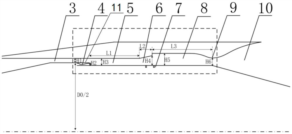
[0045] The length L1 of the mixing channel 5 is in the range of 4.3H3

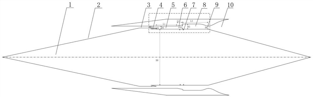
[0046] Such as figure 1 The combustion chamber of a wide-speed-range injection type rotary detonation engine shown is a cavity formed by a hollow cylindrical shell with openings at both ends and a central body 1 arranged in the shell. The cavity Including the intake passage 2, the isolation section passage 3, the mixing passage 5, the expansion passage 6, the combustion chamber cavity 8, the combustion chamber throat 9 and the tail nozzle 10 connected in sequence, the expansion passage 6 and / or the combustion chamber A fuel nozzle 7 is prov...

Embodiment 2

[0055] Combined with the flight trajectory, when flying at a low Mach number, if the flow captured by the inlet 2 is 4kg / s, the total pressure is 2atm±0.2atm.

[0056] The length L1 of the mixing channel 5 is in the range of 3.3H3

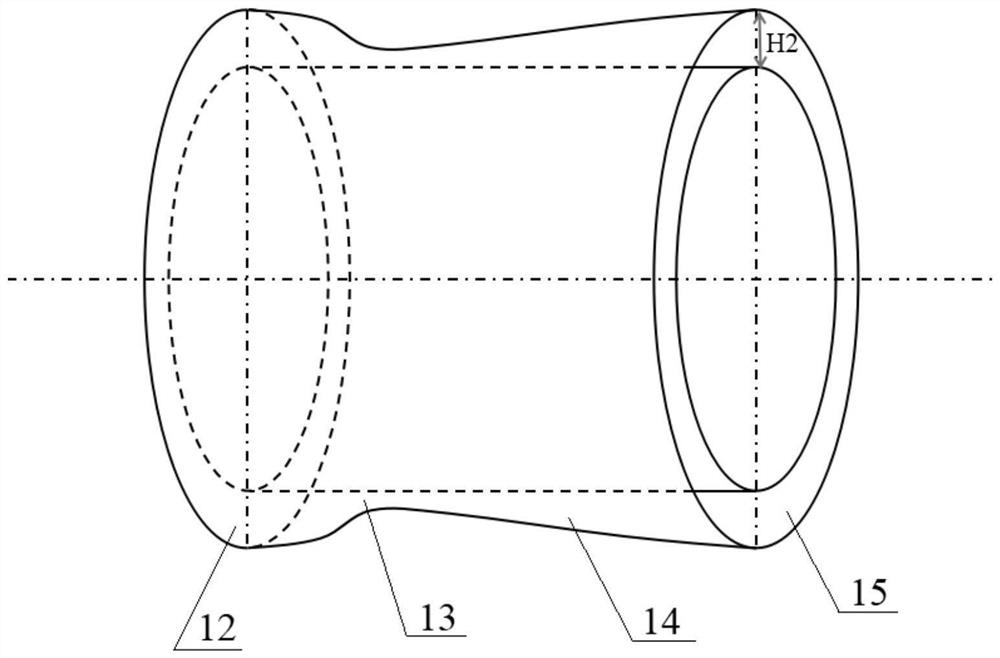
[0057] In this embodiment, the annular rocket 4 consists of eight fan-shaped rockets arranged along the circumferential direction of the central body 1, each responsible for a fan annular gap, and finally the high-temperature and high-pressure gas is ejected through the fan-shaped nozzle 16 with a height of H2. Described annular rocket 4 adopts gas oxygen kerosene rocket.

Embodiment 3

[0059] Combined with the flight trajectory, when flying at a low Mach number, if the flow captured by the inlet 2 is 4kg / s, the total pressure is 1atm±0.2atm.

[0060] The length L1 of the mixing channel 5 is in the range of 5H3

[0061] In this embodiment, the annular rocket 4 consists of twelve fan-shaped rockets arranged along the circumferential direction of the central body 1, each responsible for a fan-shaped annular seam, and finally the high-temperature and high-pressure gas is ejected through the fan-shaped nozzle 16 with a height of H2. Described annular rocket 4 adopts gas oxygen kerosene rocket.

[0062] To sum up, the present invention provides a rotary detonation ramjet combustor with gas ejection. A ring rocket is added to the front of the rotary detonati...


PUM


Abstract

The invention provides a gas injection type rotary detonation ramjet combustion chamber. The combustion chamber is a cavity defined by a shell and a center body arranged in the shell, wherein the shell is in a hollow cylinder shape, the two ends of the shell are open, the cavity comprises an air inlet channel, an isolation section channel, a mixing channel, an expansion channel, a combustion chamber cavity body, a combustion chamber throat and an exhaust nozzle which sequentially communicate, fuel nozzles are arranged at the expansion channel and / or the combustion chamber cavity body, and an annular rocket is arranged at the isolation section channel. According to the gas injection type rotary detonation ramjet combustion chamber, air is mixed and pressurized through the annular rocket, mixed airflow is converted into subsonic velocity from supersonic velocity in the expansion section, and a throttling section is formed, so that pulsating pressure generated in the combustion process ofthe combustion chamber is prevented from being transmitted to the upstream; and meanwhile, the annular rocket is adopted for ejection and pressurization, so that the combustion efficiency of the combustion chamber is improved, the flight envelope range of a rotary detonation ramjet is widened, an aircraft can normally work when the flight Mach number is low, and stable thrust is provided for theaircraft.

Description

technical field [0001] The invention relates to the technical field of aerospace engine propulsion, in particular, to a rotary detonation engine combustion chamber. Background technique [0002] The speed range of the engine is an important design index of the engine. A wide speed range means a wider application range of the engine. The larger the flight envelope range, the more practical the engine and the wider the application prospect. Conventional rotary detonation engines rely solely on the effect of air ram, so when the flight speed is low, the engine ram effect is not enough, the air boost is not obvious, and the engine thrust performance is low. [0003] In order to broaden the range of the flight envelope of the rotary detonation engine, increase its combustion efficiency, and enable it to work stably in a wider airspace, a new technology for the combustion chamber of the rotary detonation ramjet engine with gas injection is urgently needed in the industry. Conten...

Claims


Application Information

Patent Timeline
Patent Type & Authority Applications(China)
IPC IPC(8): F02K7/18F23R7/00
CPCF02K7/18F23R7/00
Inventor 孙明波顾瑞陈健蔡尊董泽宇姚轶智王泰宇
Owner NAT UNIV OF DEFENSE TECH
Why Eureka
Try Eureka