Illumination-adjustable LED intelligent plant growth lamp
A technology for growing lamps and plants, which is applied to botany equipment and methods, components of lighting devices, semiconductor devices of light-emitting elements, etc., and can solve the problems of affecting the economic benefits of planting, poor applicability, plant growth light intensity and light color fixation, etc. , to avoid poor contact, easy to install, and change the lighting range
- Summary
- Abstract
- Description
- Claims
- Application Information
AI Technical Summary
Problems solved by technology
Method used
Image
Examples
Embodiment 1
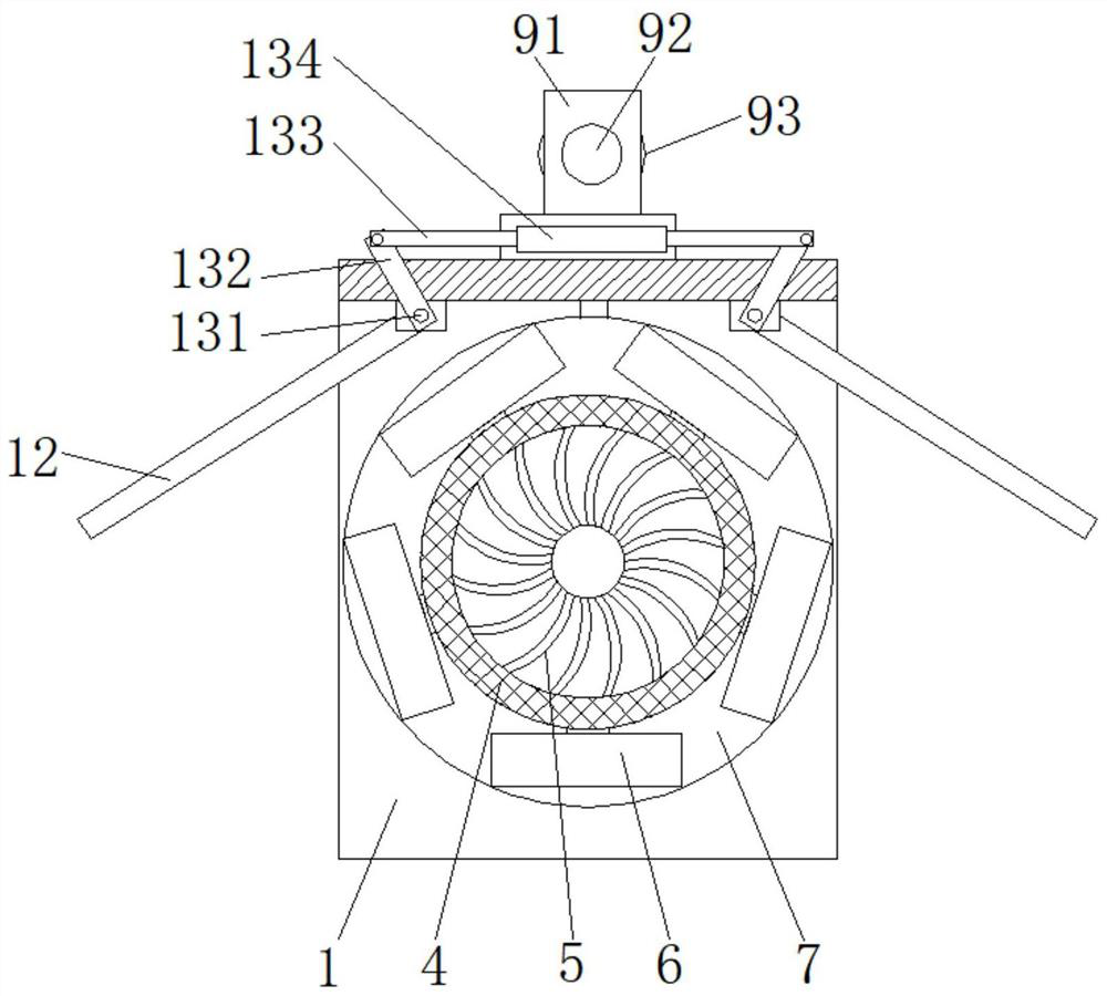
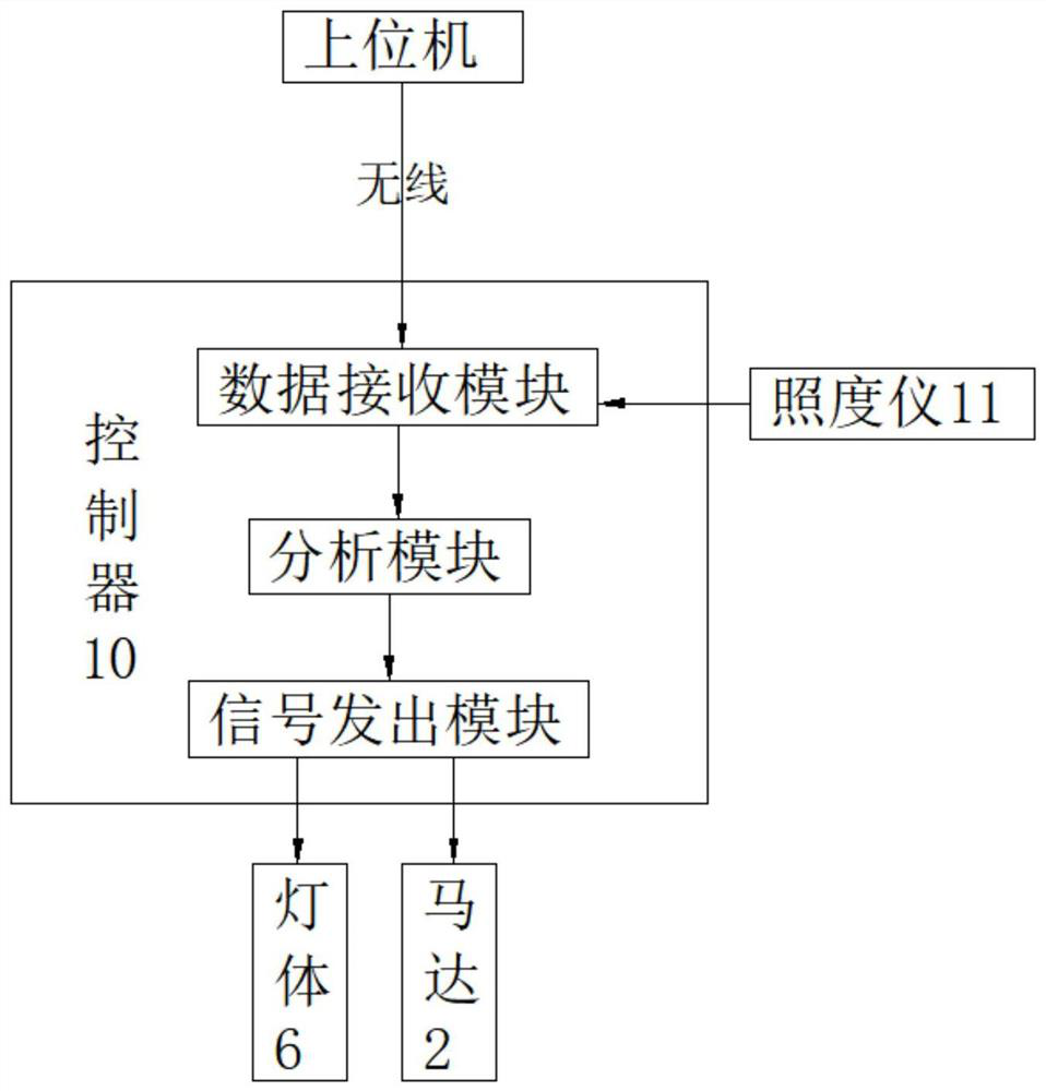
[0029] refer to Figure 1-4 , an LED plant intelligent growth lamp with adjustable illumination, U-shaped lamp housing 1 with the opening facing downwards, a motor 2 is installed on one end of the U-shaped lamp housing 1, and a cooling fan 3 is installed on the other end, the output shaft of the motor 2 passes through the U U-shaped lamp housing 1, and a lamp body installation cylinder 4 is fixedly installed, and the axes of the lamp body installation cylinder 4 and the U-shaped lamp housing 1 are collinear, and a radiator 5 is installed on the inner wall of the lamp body installation cylinder 4, and the lamp body installation cylinder A plurality of radially distributed lamp bodies 6 are installed on the outside of 4, each lamp body 6 is a full-spectrum lamp with a wavelength range of 400nm to 660nm, and a reflector 14 is installed on the outside of each lamp body 6 The reflective surface of the inner surface is a compound paraboloid, and a power supply mechanism 8 is connect...
Embodiment 2
[0032] refer to Figure 1-2 The top of the U-shaped lamp housing 1 is equipped with two symmetrically arranged hoisting mechanisms 9. The hoisting mechanism 9 includes a suspending rod 91, a rope-wrapping rod 92 and a limit ring 93. The suspending rod 91 is fixedly installed on the U-shaped lamp housing 1. The top of the top, one end of the rope-winding rod 92 is fixedly installed on the upper end of the suspension rod 91, the rope-winding rod 92 is provided with an external thread, and the inwall of the spacer ring 93 is provided with a threaded hole matched with the external thread.
[0033] The indoor or greenhouse hanging rope can be wound and bound on the rope winding rod 92, and the limit ring 93 can be rotated on the rope winding rod 92 to limit the position, which is convenient for the installation of the present invention, and at the same time, it can be adjusted by changing the winding length installation height.
Embodiment 3
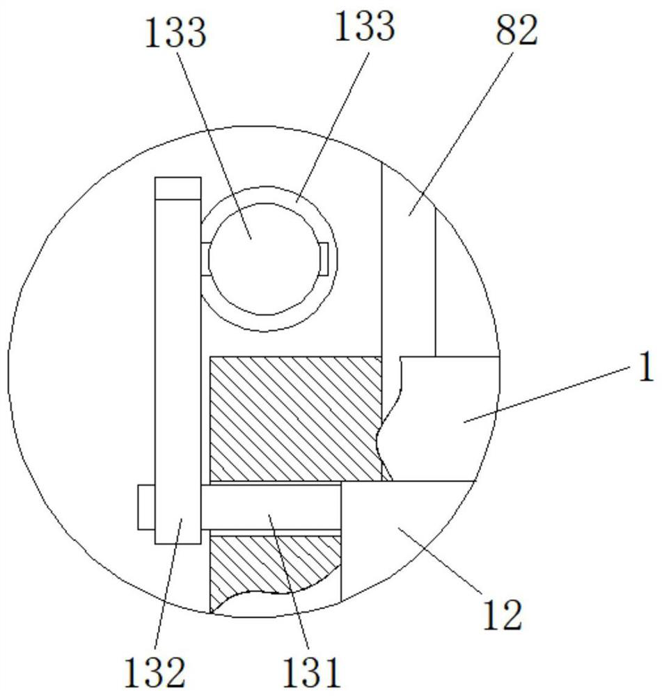
[0035] refer to Figure 1-3 , both sides of the U-shaped lamp housing 1 are hinged with reflectors 12, and both ends of the two reflectors 12 are connected with an adjustment mechanism 13, and the adjustment mechanism 13 includes two connections that are respectively fixed and installed at the ends of the two reflectors 12. Rotating rod 131, and one end of the two connecting rotating rods 131 passing through the U-shaped lamp housing 1 is fixedly equipped with a transmission rod 132, and the upper ends of the two driving rods 132 are hinged with a connecting screw 133, and the outer sides of the two connecting screw rods 133 are provided with There are external threads with opposite rotations, and an adjusting tube 134 is connected between the two connecting screws 133 , and the two ends of the adjusting tube 134 are respectively provided with threaded holes matching the two connecting screws 133 .
[0036] According to the scope of the plant, the adjusting tube 134 is rotated...
PUM
| Property | Measurement | Unit |
|---|---|---|
| wavelength | aaaaa | aaaaa |
Abstract
Description
Claims
Application Information
 - R&D
- Intellectual Property
- Life Sciences
- Materials
- Tech Scout
- Unparalleled Data Quality
- Higher Quality Content
- 60% Fewer Hallucinations
Browse by: Latest US Patents, China's latest patents, Technical Efficacy Thesaurus, Application Domain, Technology Topic, Popular Technical Reports.
© 2025 PatSnap. All rights reserved.Legal|Privacy policy|Modern Slavery Act Transparency Statement|Sitemap|About US| Contact US: help@patsnap.com


