Converter transformer network side sleeve pull rod system
A commutation and tie rod technology, applied in transformer/inductor parts, transformer/inductor coils/windings/connections, electrical components, etc., can solve internal faults of transformers, system outages, current-carrying base plates and terminal blocks The problem of loose connection, etc., can reduce the possibility of failure, stabilize the tie rod system, and reduce the assembly cost.
- Summary
- Abstract
- Description
- Claims
- Application Information
AI Technical Summary
Problems solved by technology
Method used
Image
Examples
Embodiment Construction
[0024] The present invention will be described in further detail below in conjunction with the accompanying drawings and embodiments.
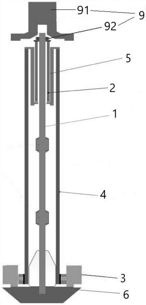
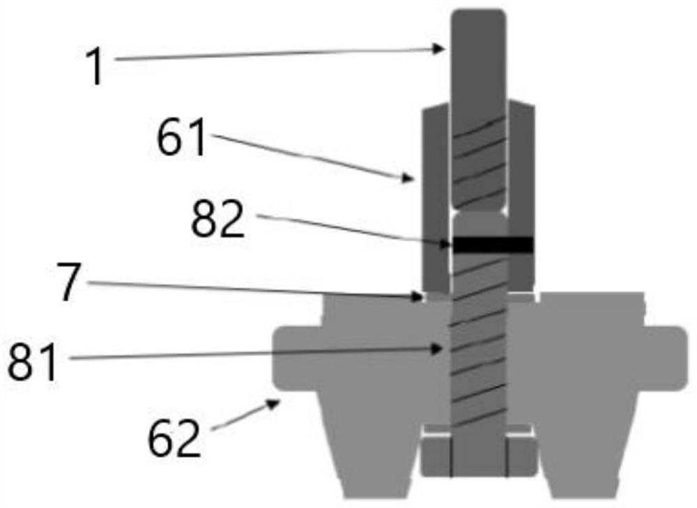
[0025] Such as figure 1 and figure 2 As shown in the example, a bushing tie rod system on the side of the converter grid disclosed in this embodiment includes a cylindrical tie rod 1, which is composed of three sets of rods connected by connecting rods. The tie rod 1 is made of steel, and the length of the tie rod 1 is 7278mm; the bottom of the tie rod 1 is connected with the wiring device 6, the top of the tie rod 1 is connected with the fixing device 9, the fixing device 9 includes a general cap 91 and the top nut 92; the bottom of the fixing device 9 is fixedly connected with a vertical compensation aluminum tube 2 , the compensation aluminum tube 2 is sleeved on the periphery of the tie rod 1, and the height of the compensation aluminum tube 2 is 3308mm.
[0026] A number of current-carrying bottom plates 3 are evenly installed on the t...
PUM
| Property | Measurement | Unit |
|---|---|---|
| height | aaaaa | aaaaa |
Abstract
Description
Claims
Application Information
 - R&D
- Intellectual Property
- Life Sciences
- Materials
- Tech Scout
- Unparalleled Data Quality
- Higher Quality Content
- 60% Fewer Hallucinations
Browse by: Latest US Patents, China's latest patents, Technical Efficacy Thesaurus, Application Domain, Technology Topic, Popular Technical Reports.
© 2025 PatSnap. All rights reserved.Legal|Privacy policy|Modern Slavery Act Transparency Statement|Sitemap|About US| Contact US: help@patsnap.com


