A bushing tie rod system on the side of the transformer grid
A commutation and pull rod technology, which is applied to transformer/inductor parts, transformer/inductor coils/windings/connections, electrical components, etc. System outage and other problems, to reduce the loosening of the tie rod and the wiring device, reduce the possibility of failure, and stabilize the tie rod system
- Summary
- Abstract
- Description
- Claims
- Application Information
AI Technical Summary
Problems solved by technology
Method used
Image
Examples
Embodiment Construction
[0024] The present invention will be further described in detail below with reference to the accompanying drawings and examples.
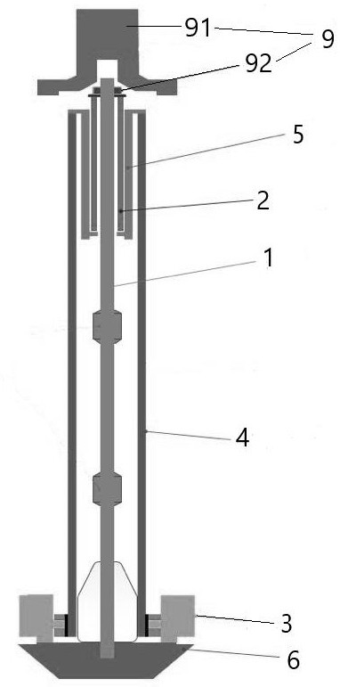
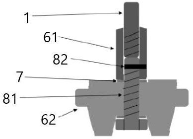
[0025] like figure 1 with figure 2 As shown, the present embodiment disclosed, a converter variable web side sleeve tube rod system, including a cylindrical tie rod 1, and the pulley 1 consists of three sets of struts, and the tie rod 1 is made of steel, the length of the lever 1 is 7278mm; the bottom of the pulley 1 is connected to the wiring device 6, and the top of the tie rod 1 is connected to the fixing device 9, and the fixing device 9 includes a detachable cap 91 and a top nut 92; the bottom fixing of the fixing device 9 is fixedly connected to the aluminum tube 2 The compensation of the aluminum tube 2 is set in the periphery of the tie rod 1, and the height of the aluminum tube 2 is 3308 mm.
[0026] The top of the wiring device 6 is uniformly mounted along the circumference, and the inner side surface of the carrier base plate 3 is fixedly co...
PUM
| Property | Measurement | Unit |
|---|---|---|
| height | aaaaa | aaaaa |
Abstract
Description
Claims
Application Information
 - R&D
- Intellectual Property
- Life Sciences
- Materials
- Tech Scout
- Unparalleled Data Quality
- Higher Quality Content
- 60% Fewer Hallucinations
Browse by: Latest US Patents, China's latest patents, Technical Efficacy Thesaurus, Application Domain, Technology Topic, Popular Technical Reports.
© 2025 PatSnap. All rights reserved.Legal|Privacy policy|Modern Slavery Act Transparency Statement|Sitemap|About US| Contact US: help@patsnap.com


