Battery module, power battery pack and vehicle

A battery module and module technology, applied in the field of vehicles, can solve the problems of small exhaust aperture of the exhaust pipe 100, thermal runaway of a single battery, long exhaust path of the exhaust pipe 100, etc., to reduce the probability of fire and explosion , to avoid the effect of further temperature rise and further increase of internal pressure

Inactive Publication Date: 2020-09-15
BYD CO LTD
View PDF6 Cites 4 Cited by
  • Summary
  • Abstract
  • Description
  • Claims
  • Application Information

AI Technical Summary

Problems solved by technology

[0003] However, a plurality of single cells 20 sharing one exhaust channel 100 has the following disadvantages: first, as figure 2 As shown, since a plurality of single cells 100 share one exhaust duct 100, during the continuous exhaust process, the high-temperature gas continuously heats the single cells 20 on the exhaust path, causing the temperature of other single cells to rise continuously, exacerbating the Thermal diffusion leads to thermal runaway of more single batteries; second, the exhaust path of the exhaust pipe 100 is too long, and it is not easy to avoid the wire harness in the battery module during the layout, and the high-temperature gas may burn other wire harnesses during the exhaust process Third, due to space constraints, the exhaust pipe 100 has a small exhaust aperture and a slow exhaust speed, and a large amount of gas generated by thermal runaway is too late to be discharged from the battery module, which easily leads to thermal runaway monomers The temperature of the battery cell rises rapidly, and the internal pressure of the battery module continues to increase, which may eventually cause the battery module to catch fire and explode

Method used


Image

  • Battery module, power battery pack and vehicle
  • Battery module, power battery pack and vehicle
  • Battery module, power battery pack and vehicle

Examples


Embodiment Construction

[0046] Specific embodiments of the present disclosure will be described in detail below in conjunction with the accompanying drawings. It should be understood that the specific embodiments described here are only used to illustrate and explain the present disclosure, and are not intended to limit the present disclosure.

[0047] In this disclosure, unless stated to the contrary, the used orientation words such as "upper and lower" generally have the same meaning as upper and lower when the vehicle is running normally, and "inner and outer" are the outlines of related parts inside and outside.

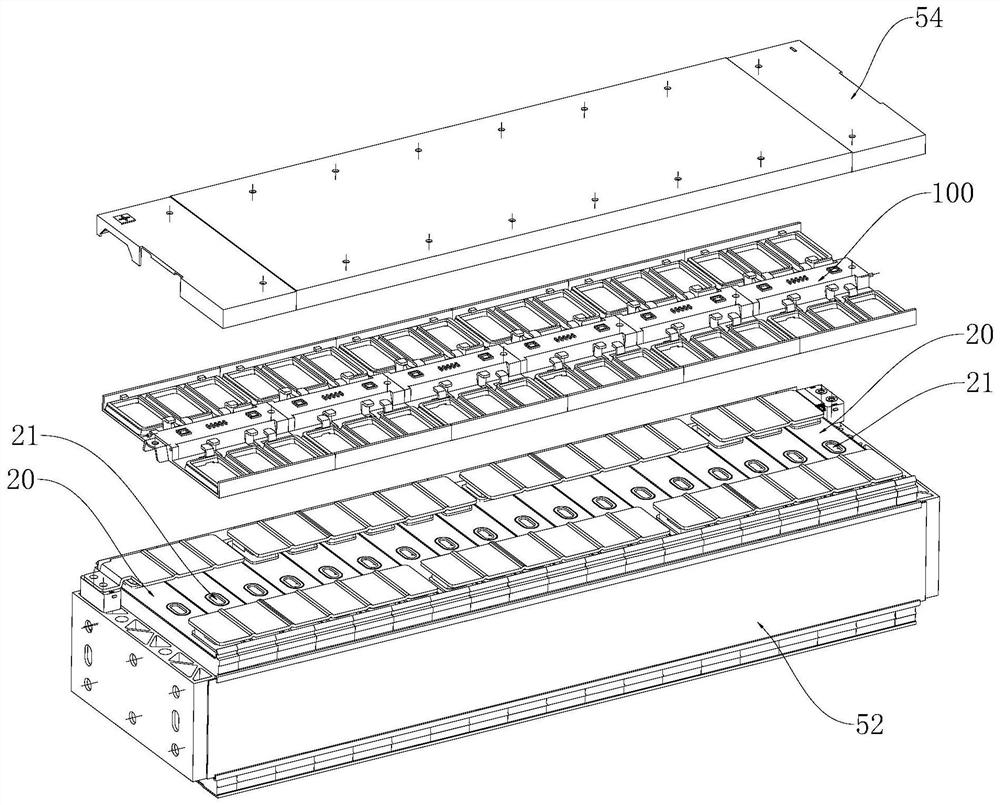
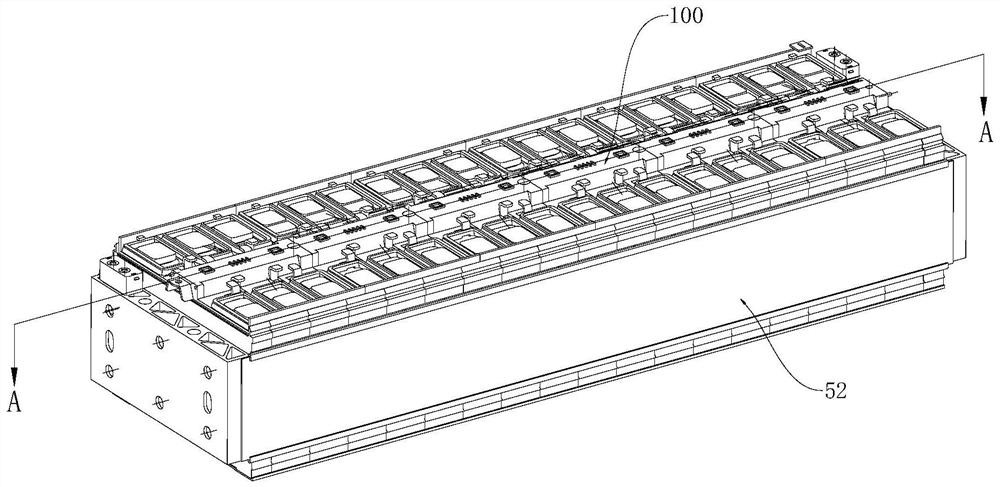
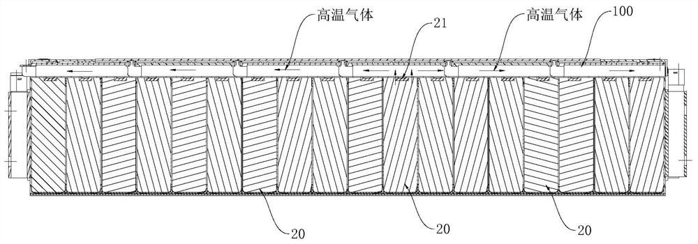
[0048] like Figure 4 to Figure 8 As shown, according to one aspect of the present disclosure, a battery module is provided. The battery module includes a module end cover, a plurality of single cells 20 and a cell protection cover 10. The holes 30 and the vent holes 30 are arranged opposite to the explosion-proof valve 21 on the single battery 20 and correspond to each other. The air...


PUM


Abstract

The invention relates to a battery module, a power battery pack and a vehicle. The battery module comprises a module end cover, a plurality of monomer batteries and a monomer protective cover, whereina plurality of gas exhaust holes are formed in the module end cover, the monomer exhaust holes and explosion-proof valves on the monomer batteries are oppositely arranged and are in one-to-one correspondence, a gas guide cylinder is formed on the monomer protective cover and comprises a cylinder body, a first port and a second port, the periphery of the first port surrounds the explosion-proof valve, the periphery of the second port surrounds the gas exhaust hole, and gas exhausted by the explosion-proof valve sequentially passes through the first port, the cylinder body and the second port and then reaches the gas exhaust hole. According to the invention, each monomer battery in the battery module is provided with an independent gas exhaust channel, so that heat diffusion can be avoided,thermal runaway cannot be transferred to other single batteries, and the gas exhaust path of the gas exhaust channel is shortened, so that gas cannot be retained in the battery module and can be quickly exhausted while other parts in the battery module cannot be damaged.

Description

technical field [0001] The present disclosure relates to the field of electric vehicles, and in particular, to a battery module, a power battery pack with the battery module, and a vehicle with the power battery pack. Background technique [0002] like Figure 1 to Figure 3 As shown, there are several single cells 20 and an exhaust pipe 100 in the battery module, and several single cells 20 share one exhaust pipe 100. , the explosion-proof valve 21 of the thermal runaway single battery 20 will be opened, and the high-temperature gas inside the single battery 20 can be discharged along the exhaust pipe 100 to release the internal pressure of the battery module. [0003] However, a plurality of single cells 20 sharing one exhaust channel 100 has the following disadvantages: first, as figure 2 As shown, since a plurality of single cells 100 share one exhaust duct 100, during the continuous exhaust process, the high-temperature gas continuously heats the single cells 20 on the...

Claims


Application Information

Patent Timeline
Patent Type & Authority Applications(China)
IPC IPC(8): H01M2/12H01M2/10B60L50/64
CPCY02T10/70
Inventor 曾毅郑卫鑫
Owner BYD CO LTD
Why Eureka
Try Eureka