Electric actuator

An electric actuator and power supply terminal technology, applied in the direction of current collectors, electric components, rotary current collectors, etc., can solve the problems of unstable contact and achieve the effect of stable electrical connection

Inactive Publication Date: 2020-09-15
TOKYO PARTS IND CO LTD
View PDF2 Cites 0 Cited by
  • Summary
  • Abstract
  • Description
  • Claims
  • Application Information

AI Technical Summary

Problems solved by technology

[0008] In the above-mentioned conventional actuator, although the connection of the power supply terminal on the connector side and the power supply terminal on the motor side may not require soldering, spot welding, etc., there is a possibility that the two power supply terminals may contact each other due to vibration of the motor itself or the vehicle. The problem that the contact of the part becomes unstable

Method used


Image

  • Electric actuator
  • Electric actuator
  • Electric actuator

Examples


Embodiment Construction

[0062] Hereinafter, embodiments of the electric actuator of the present invention will be described with reference to the drawings. In addition, in this specification, the upper case and the lower case are used as the two cases constituting the outer case, but this is for convenience of description, and it is not intended to be limited to the configuration of the upper case and the lower case. , up and down can be reversed, and left and right can also be used. Therefore, for example, the "upper case" may be renamed as the "lower case", and the "lower case" may be renamed as the "upper case".

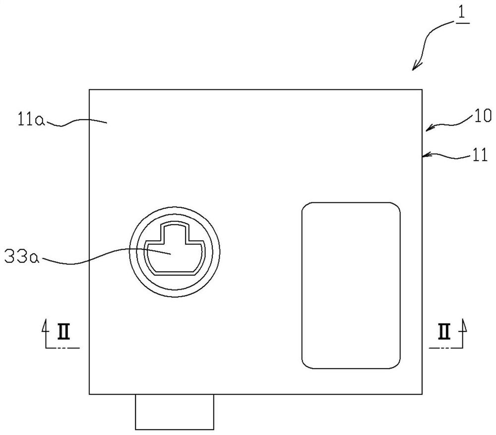
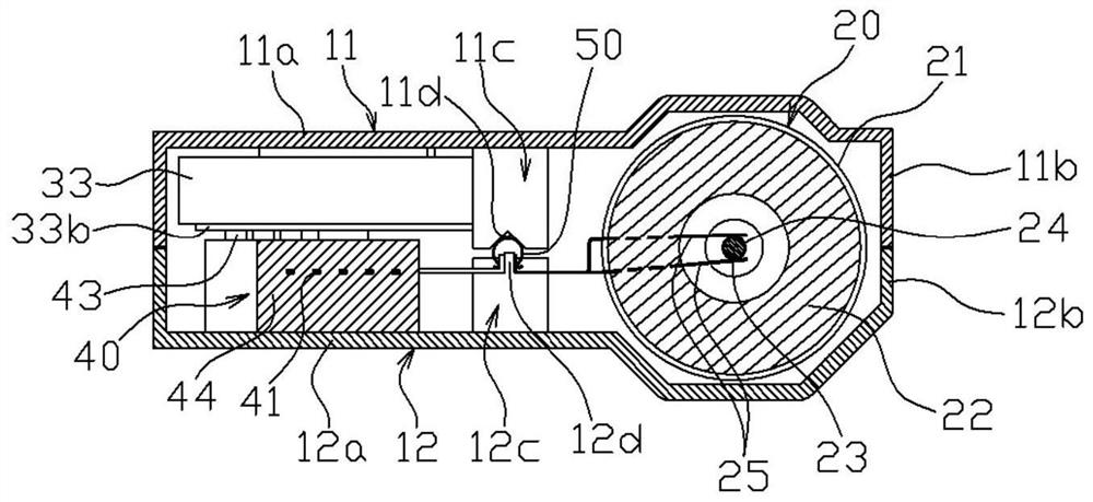
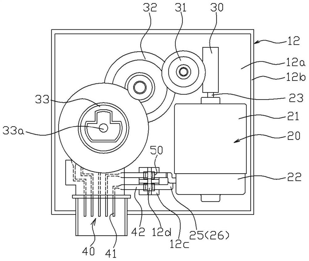
[0063] The electric actuator 1 according to the first embodiment of the present invention can be used, for example, as a drive source of an air flow regulating valve of a vehicle air conditioner, and is used Figure 1 to Figure 7 Describe in detail.

[0064] The electric actuator 1 of this example has a motor 20 , a worm gear 30 , intermediate gears 31 and 32 , an output gear 33 , a co...


PUM


Abstract

The invention provides an electric actuator capable of surely performing electrical connection between a power supply terminal of a motor and a connector terminal. A brush motor (20) having a power supply terminal (26) and a connector terminal (42) are housed in a housing (1) made of an insulating resin. One end of the power supply terminal (26) and one end of a connector terminal (42) are sandwiched by a clip terminal (50) in a state in which an interval adjusting part (12d) formed in a housing (10) is held between one end of the power supply terminal (26) and one end of the connector terminal (26), whereby the power supply terminal (26) and the connector terminal (42) are electrically connected to each other.

Description

technical field [0001] The present invention relates to an electric actuator provided with a motor inside a casing. Background technique [0002] For example, an actuator using an electric motor is known as a drive source for an airflow regulating valve provided in an air-conditioning passage of a vehicle. [0003] As such a motor actuator, for example, Patent Document 1 discloses an actuator including a motor, a reduction gear set, a rotation sensor, and an upper case and a lower case that accommodate them. In this motor actuator, one end of a pair of actuator connector terminals accommodated in the connector housing is connected to a pair of power supply terminals of the motor. [0004] In addition, Patent Document 2 describes an actuator including a motor having a pair of power supply terminals, and a pair of power supply terminals connected to the connector-side terminals and contacting while applying elastic force to the power supply terminals of the motor. device. ...

Claims


Application Information

Patent Timeline
IPC IPC(8): H02K5/22H01R39/36
CPCH01R39/36H02K5/225
Inventor 小柳尚久
Owner TOKYO PARTS IND CO LTD
Why Eureka
Try Eureka