
PCB circuit spraying etching machine

A technology of spray etching and wiring, which is applied in the direction of printed circuit, printed circuit manufacturing, electrical components, etc., can solve the problems such as the edge etching precision is lower than the middle position, the side etching amount of the etched outer layer circuit increases, and the etching precision is inconsistent, etc., to achieve Improve the etching accuracy and quality, improve the etching accuracy and uniformity, and achieve the same etching degree

Inactive Publication Date: 2020-09-15
龚明瀚
View PDF0 Cites 6 Cited by
  • Summary
  • Abstract
  • Description
  • Claims
  • Application Information

AI Technical Summary

Problems solved by technology

[0003] When the spray equipment sprays and etchs the upper and lower surfaces of the PCB, the liquid medicine will remain on the upper surface of the PCB after the upper surface receives the etching, forming a "pool effect", which will affect the subsequent reaction of the liquid medicine. A certain barrier will lead to inconsistent etching precision between the upper surface and the lower surface. At the same time, it will increase the amount of side etching when etching the outer layer circuit, resulting in a decrease in etching accuracy. Similarly, some reacted liquid medicine will remain on the lower surface, which will affect the subsequent reaction. still have an impact
[0004] The spray sprayed by the spray equipment is fan-shaped, and there is some cross coverage between them. With the swing of the spray equipment, the edge of the spray equipment has a smaller degree of etching coverage on the edge of the PCB than the middle position, which results in edge etching accuracy. far below the middle

Method used


Image

  • PCB circuit spraying etching machine
  • PCB circuit spraying etching machine
  • PCB circuit spraying etching machine

Examples


Embodiment Construction

[0028] The following will clearly and completely describe the technical solutions in the embodiments of the present invention with reference to the accompanying drawings in the embodiments of the present invention. Obviously, the described embodiments are only some of the embodiments of the present invention, not all of them. Based on the embodiments of the present invention, all other embodiments obtained by persons of ordinary skill in the art without making creative efforts belong to the protection scope of the present invention.

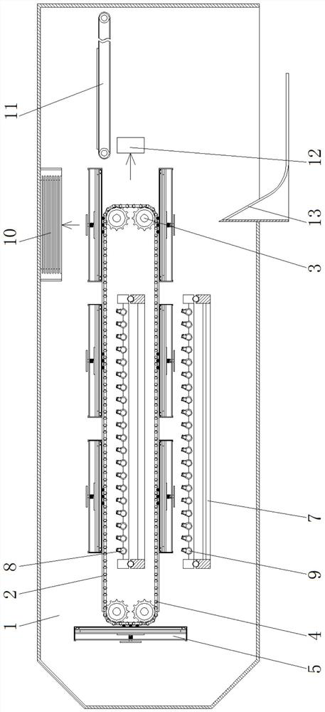
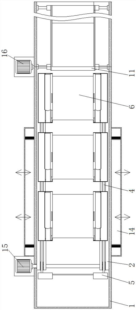
[0029] see Figure 1-9 , a PCB line spray etching machine, including a fixed box 1, PCB6 and a booster pump, the inside of the fixed box 1 is fixedly installed with a fixed base 2, and the inside of the fixed base 2 is movably socketed with a gear shaft 3, the gear shaft Chain 4 is installed movablely on 3, and chain 4 is fixedly connected with clamping device 5, and the inner cavity of fixed box 1 is respectively positioned between fixed base 2 ...


PUM


Abstract

The invention relates to the technical field of etching machines, and discloses a PCB circuit spraying etching machine. The PCB circuit spraying etching machine comprises a fixed box, a PCB and a booster pump, wherein fixed bases are fixedly installed in the fixed box, the interior of each fixed base is movably connected with a gear shaft in a sleeving manner, a chain is movably installed on the gear shaft, the chain is fixedly connected with a clamping device, and supporting frames are fixedly installed in an inner cavity of the fixed box and located between the fixed bases and below the fixed bases respectively. Through the arrangement of an upper spraying device and a lower spraying device, a liquid medicine is jetted upwards; Meanwhile, through the arrangement of the chain and the clamping device, the PCB passes through the area where the upper spraying device sprays the liquid medicine at a constant speed, gap etching is carried out on the bottom surface of the PCB, then the PCB is turned over and passes through the area where the lower spraying device sprays the liquid medicine so as to carry out gap etching on the other surface of the PCB, the pool effect is effectively prevented from being formed on the PCB, and thus the etching precision and uniformity are improved.

Description

technical field [0001] The invention relates to the technical field of etching machines, in particular to a PCB circuit spray etching machine. Background technique [0002] With the rapid development of electronic products, new electronic placement technologies continue to emerge, which promotes the development of PCB design in the direction of lightness, thinness, shortness, smallness and multi-function. PCB circuits are becoming denser and denser. One process is the etching section. The etching equipment uses a roller to transfer the PCB to a pair of opposing spray equipment to etch the upper surface and the lower surface of the PCB respectively. However, the current spray etching equipment has certain shortcomings, as follows: [0003] When the spray equipment sprays and etchs the upper and lower surfaces of the PCB, the liquid medicine will remain on the upper surface of the PCB after the upper surface receives the etching, forming a "pool effect", which will affect the ...

Claims


Application Information

Patent Timeline
Patent Type & Authority Applications(China)
IPC IPC(8): H05K3/06
CPCH05K3/068
Inventor 龚明瀚
Owner 龚明瀚
Learn More