A multi-parameter automatic control and efficient rotary spray etching system
What is Al technical title?
Al technical title is built by PatSnap Al team. It summarizes the technical point description of the patent document.
A spray etching, multi-parameter technology, applied in printed circuit, electrical components, chemical/electrolytic method to remove conductive materials, etc., can solve the problem of etchant concentration and pressure reduction, pool effect, etchant supply and flow distribution. Uniformity and other issues
Active Publication Date: 2021-09-07
XI AN JIAOTONG UNIV
View PDF8 Cites 0 Cited by
Summary
Abstract
Description
Claims
Application Information
AI Technical Summary
This helps you quickly interpret patents by identifying the three key elements:
Problems solved by technology
Method used
Benefits of technology
Problems solved by technology
[0003] The existing invention patent CN108034946A adopts that the etching substrate is fixed in the center of the rotating shaft in a regular hexagonal shape, and the nozzle hole is moved in translation around the surrounding for spray etching. However, due to its non-stop movement, the supply and flow distribution of the etching liquid will appear uneven. The situation is extremely unfavorable to the etching effect; the sprayed etching solution will collide with the etching solution falling from the etching substrate after etching, which will cause the concentration and pressure of the etching solution to decrease and pools will appear on the etching substrate below effect; while the entire system is manually regulated and cannot be simultaneously and associated with the control and monitoring of multiple parameters; and the existing etching system is only for flat plate etching, etching plates of other shapes such as cylindrical, concave Can not be retrofitted and well applied
Method used
Image
Click on the blue label to locate the original text in one second.
Reading with bidirectional positioning of images and text.
Examples
Embodiment Construction
[0025] The present invention will be further described in detail below in conjunction with the accompanying drawings.
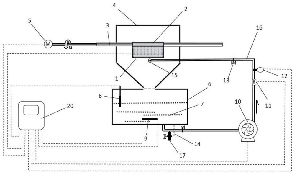
[0026] figure 1 It is a structural diagram of the spray etching system of the present invention.
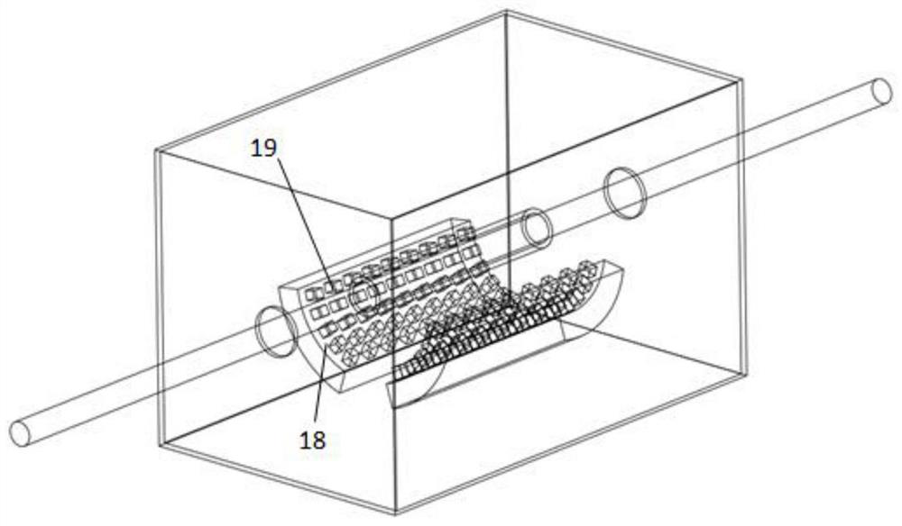
[0027] The multi-parameter automatic regulation high-efficiency rotary spray etching system includes etching liquid injection device (1), rotating guide rod (3), etching box (4), motor (5), etching liquid collection box (6), redox meter ( 8), heater (9), centrifugal pump (10), flow meter (11), pressure gauge (12), delivery pipe (16), automatic control center (20). Among them, the etching substrate (2) is fixed on the rotating guide rod (3), and the rotating guide rod (3) is driven by the motor (5); the etching liquid injection device (1) is arranged in the etching box (4), and has two arcs There is an array of fixed nozzle holes (19) on the curved spray surface (18), and the etching solution (7) is sprayed vertically from the two curved spray surfaces of the e...
PUM
Abstract
A multi-parameter automatic control and high-efficiency rotary spray etching system, which includes an automatic control center, an etching substrate, a motor, an etching box, an etching solution injection device, a rotating guide rod, a pressure gauge, a flow meter, a centrifugal pump, and an etching solution collection box , ORP (oxidation‑reduction potential) redox meter, heater, delivery pipe, separator, filter, impurity cleaning device, etc. The etching solution flows from the etching collection box into the etching box under the driving of the centrifugal pump, and is sprayed from the nozzle hole of the etching solution spray device to the etching substrate to etch the etching substrate exposed between the photoresists. The invention connects the real-time parameters of the etching liquid spray device, pressure gauge, flow meter, heater and ORP redox meter into an automatic control center, and adjusts the motor power, centrifugal pump power, heater power, etching liquid through real-time feedback concentration and location of the etched substrate. Thus, the entire system is maintained in an optimal stable state that satisfies the given parameters for etching.
Description
technical field [0001] The invention belongs to the technical field of mechanical micromachining, and particularly relates to a spray etching device which can be used for preparing printed circuit board heat exchangers or cylindrical microchannel heat exchangers and even complex surface structures. Background technique [0002] The existing spray etching technology is mainly aimed at flat plate etching. A spray etching system with recyclable etching solution can be designed, and the etching effect under different etching conditions can be studied by adjusting various etching parameters. [0003] The existing invention patent CN108034946A adopts that the etching substrate is fixed in the center of the rotating shaft in a regular hexagonal shape, and the nozzle hole is moved in translation around the surrounding for spray etching. However, due to its non-stop movement, the supply and flow distribution of the etching liquid will appear uneven. The situation is extremely unfavor...
Claims
Application Information
Patent Timeline
Application Date:The date an application was filed.
Publication Date:The date a patent or application was officially published.
First Publication Date:The earliest publication date of a patent with the same application number.
Issue Date:Publication date of the patent grant document.
PCT Entry Date:The Entry date of PCT National Phase.
Estimated Expiry Date:The statutory expiry date of a patent right according to the Patent Law, and it is the longest term of protection that the patent right can achieve without the termination of the patent right due to other reasons(Term extension factor has been taken into account ).
Invalid Date:Actual expiry date is based on effective date or publication date of legal transaction data of invalid patent.