
Rotary focusing device for laser drilling of thin-rod object

A technology of rotating focusing and laser drilling, which is applied in laser welding equipment, applications, food science, etc., and can solve problems such as increasing structural difficulty and increasing mechanical failure rates

Pending Publication Date: 2020-09-18
梅林 +1
View PDF0 Cites 2 Cited by
  • Summary
  • Abstract
  • Description
  • Claims
  • Application Information

AI Technical Summary

Problems solved by technology

Our company has also developed related structures. These punching methods are feasible, but multiple thin rod objects must be rotated at the same time, which increases the difficulty of the structure and increases the mechanical failure rate.

Method used


Image

  • Rotary focusing device for laser drilling of thin-rod object
  • Rotary focusing device for laser drilling of thin-rod object
  • Rotary focusing device for laser drilling of thin-rod object

Examples


Embodiment Construction

[0026] Specific embodiments of the present invention are described in detail below, but it should be understood that the protection scope of the present invention is not limited by the specific embodiments.

[0027] Unless expressly stated otherwise, throughout the specification and claims, the term "comprise" or variations thereof such as "includes" or "includes" and the like will be understood to include the stated elements or constituents, and not Other elements or other components are not excluded.

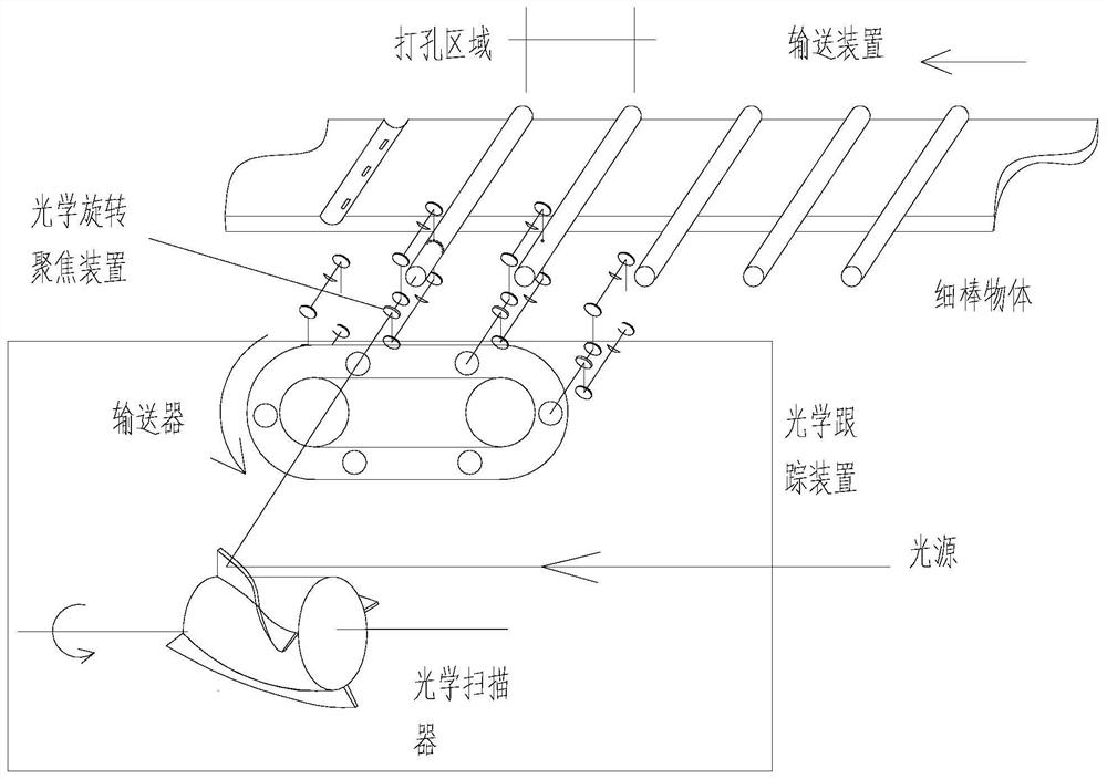
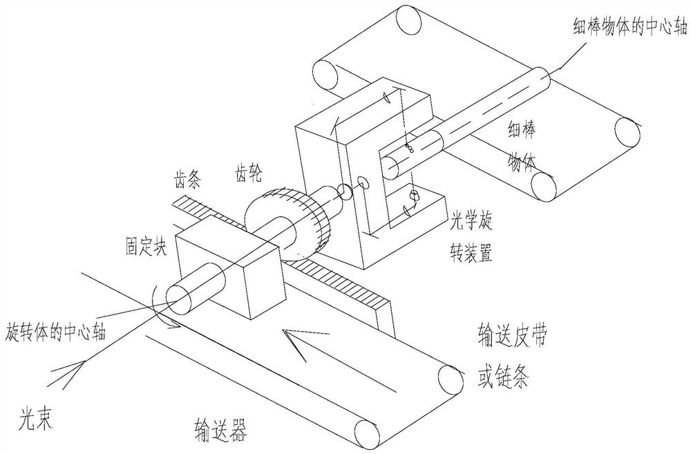
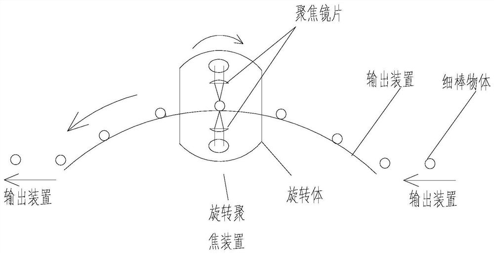
[0028] like figure 1 As shown, a rotating focusing device for online thin rod laser drilling is composed of the following components: a conveying device, a thin rod object, an optical rotating focusing device, an optical tracking device, and a laser light source.

[0029] The conveying device for cigarettes has a conveying device suitable for high-speed continuous operation or a conveying device for slow gap operation. The conveying device for high-speed continuous operation ...


PUM


Abstract

The invention discloses a rotary focusing device for laser drilling of a thin rod object. The rotary focusing device is arranged on one side of a cigarette conveying device, is used for drilling cigarettes and mainly comprises an optical rotary focusing device, and the optical rotary focusing device rotates around a single cigarette at a high speed and emits laser to the surface of the cigarettes;a traditional perforating thought is changed through the design, and multiple cigarettes can be drilled at the same time under the condition that the cigarettes are not moved.

Description

Technical field: [0001] The invention belongs to the field of laser drilling equipment, in particular to a rotating focusing device for laser drilling of thin rod objects. Background technique: [0002] For a long time, the online punching of thin rod objects has been carried out by either rotating the thin rod object 360° around its axis in situ, and then piercing by a fixed focusing device; The axis of itself rotates 360°, during which, the laser tracks the running track of the thin rod object by scanning method to perforate. Our company has also developed related structures. These methods of punching holes are feasible, but multiple thin rod objects must be rotated at the same time, which increases the difficulty of the structure and increases the mechanical failure rate. [0003] The information disclosed in this Background section is only for enhancing the understanding of the general background of the present invention and should not be taken as an acknowledgment or a...

Claims


Application Information

Patent Timeline
IPC IPC(8): A24C5/60B23K26/382B23K26/04B23K26/06B23K26/08
CPCA24C5/606B23K26/382B23K26/04B23K26/0643B23K26/0648B23K26/0884
Inventor 梅林韩梅玲吴君映
Owner 梅林
Learn More