
Patsnap Eureka
For R&D, Patsnap Eureka makes reading and utilizing patents & technical documents easy.
Patsnap Eureka AIR
Designed for self-driven R&D workflows. Generate viable solutions, solve complex R&D challenges, empower your innovation with AI.

Patsnap Eureka Materials
Designed for material experts only. Revolutionize your material R&D, from search, analyze, to developing new materials.

TechResearch
Generate reliable direction feasibility study reports for your R&D in just a few steps.

TechSeek
Discover and master advanced knowledge NOW. Basics, ideas, possibilities, all at once.

TechMind
As an expert in R&D Theories, TechMind can generates customized viable solutions instantly.

TechRisk
Analyze your overall solution with one click, know your potential R&D risks in advance.

TechMonitor
Get weekly tech updates, stay abreast of the latest tech innovations and key insights.
Forming and assembling method for arranging spiral heat tracing pipe on outer surface of thick-wall container barrel
The technology of the outer surface of the cylinder and the thick-walled container is applied in the field of manufacturing the preheating and thermal insulation structure of the shell of the pressure vessel, which can solve the problems of difficulty in fitting, difficult to guarantee the forming size, complicated forming of the bent pipe, etc., so as to achieve a simple forming process and reduce the difficulty of manufacturing. , to ensure the effect of preheating insulation effect
- Summary
- Abstract
- Description
- Claims
- Application Information
AI Technical Summary
Problems solved by technology
Method used
Image

Examples
specific Embodiment approach 1
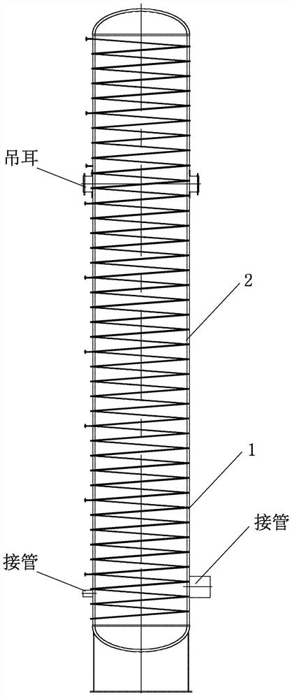
[0039] Specific implementation mode one: combine Figure 2 to Figure 7 To illustrate this embodiment, the method for forming and assembling a spiral heating pipe arranged on the outer surface of a thick-walled container cylinder in this embodiment includes the following steps:
[0040] Step 1: First draw four centerlines, the position line of the inlet and outlet of the heating pipe and the spiral line on the outer surface of the cylinder body 1;
[0041] Step 2: Turn the roller frame 4 so that the bending position is at the lowest point, leave enough margin for one end of the pipe used to bend into the heat tracing pipe 2 according to the extension direction of the marked helix and weld it firmly with the cylinder body 1, And move the backing device 3 to the side below the cylinder body 1;
[0042] Step 3: Rotate the roller frame 4, and at the same time, the operator holds one end of the pipe, moves the pipe and the backing device, so that the pipe is wound on the cylinder b...
specific Embodiment approach 2
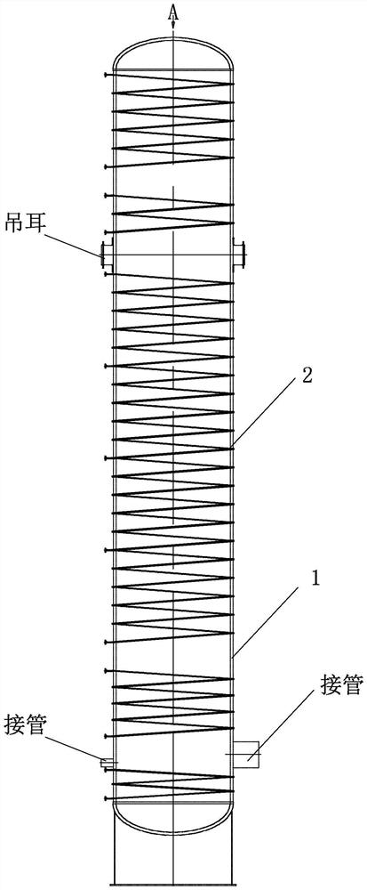
[0049] Specific implementation mode two: combination Figure 7 This embodiment will be described. In this embodiment, before step 1 is performed, the cylinder body 1 is hoisted and placed on two roller frames 4 with proper spacing. Other compositions and connections are the same as in the first embodiment.
specific Embodiment approach 3
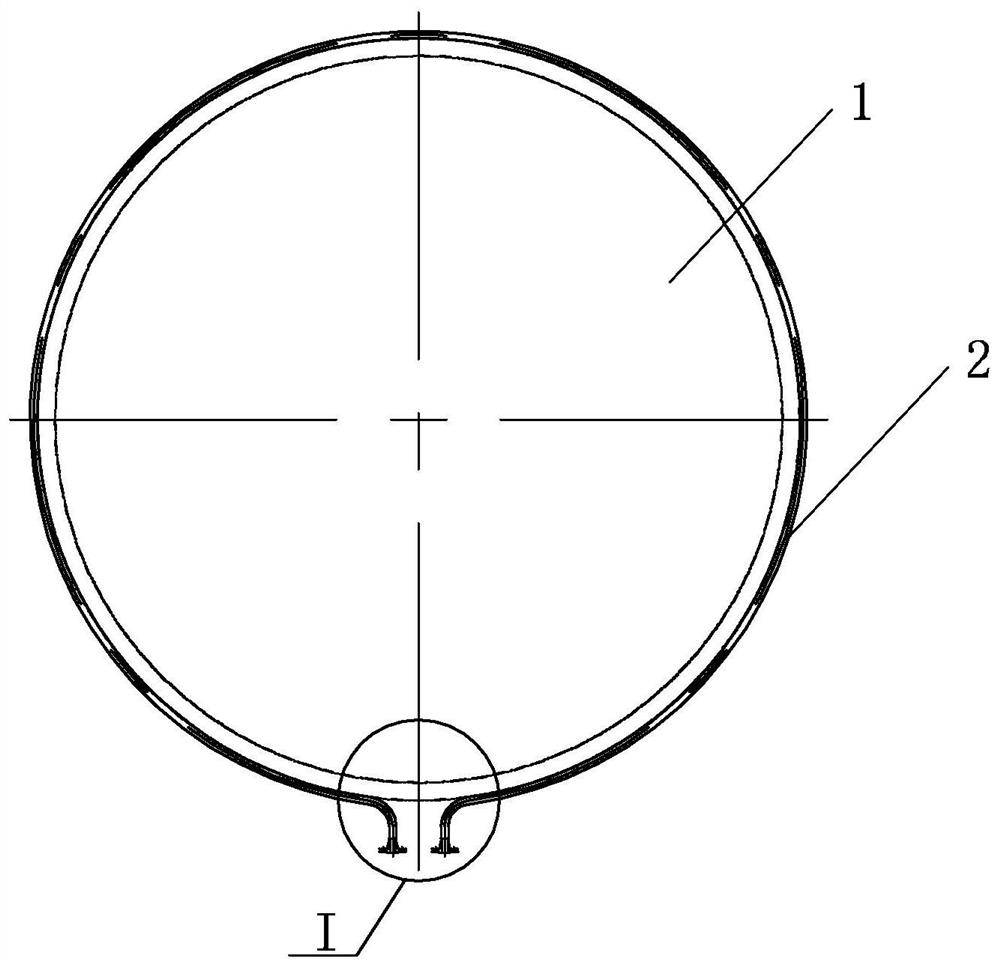
[0050] Specific implementation mode three: combination Figure 7 To illustrate this embodiment, the steps of drawing the helical line of the heat tracing pipe 2 on the outer surface of the cylinder 1 in step 1 of this embodiment are as follows:
[0051] Step 11: Draw four centerlines on the outer surface of the cylinder body 1;
[0052] Step 1 and 2: According to the design drawings, draw the inlet and outlet position lines of the heat tracing pipe 2 on the outer surface of the cylinder body 1;
[0053] Step 1 and 3: According to the design drawing, draw the position line of the heat tracing pipe 2 on the outer surface of the cylinder body 1 using a double helix line.
[0054]Such setting ensures that the winding position of the heat tracing pipe 2 can meet the design requirements when winding. Other compositions and connections are the same as those in Embodiment 1 or Embodiment 2.
PUM
 Abstract
Description
Claims
Application Information
 - R&D Engineer
- R&D Manager
- IP Professional
- Industry Leading Data Capabilities
- Powerful AI technology
- Patent DNA Extraction
Browse by: Latest US Patents, China's latest patents, Technical Efficacy Thesaurus, Application Domain, Technology Topic, Popular Technical Reports.
© 2024 PatSnap. All rights reserved.Legal|Privacy policy|Modern Slavery Act Transparency Statement|Sitemap|About US| Contact US: help@patsnap.com