
Draught fan rotor and paired wheel disassembly device

A technology of dismantling device and induced draft fan, which is applied in metal processing, metal processing equipment, manufacturing tools, etc., can solve the problems of high economic cost, hidden safety hazards, and difficulty in manual disassembly, and achieves convenient axial movement and convenient support for the opposite wheel. Effect

Inactive Publication Date: 2020-09-18
华电呼图壁能源有限公司热电厂
View PDF9 Cites 1 Cited by
  • Summary
  • Abstract
  • Description
  • Claims
  • Application Information

AI Technical Summary

Problems solved by technology

[0005] Aiming at the deficiencies of the prior art, the present invention provides a device for removing the opposite wheel of the induced draft fan rotor, which solves the problem that when the opposite wheel is disassembled from the rotor shaft, due to the heavy weight of the opposite wheel, manual disassembly is difficult and there is a certain degree of safety. Hidden dangers, while using other mechanical equipment, the economic cost is high and the problem is relatively inconvenient

Method used


Image

  • Draught fan rotor and paired wheel disassembly device
  • Draught fan rotor and paired wheel disassembly device
  • Draught fan rotor and paired wheel disassembly device

Examples


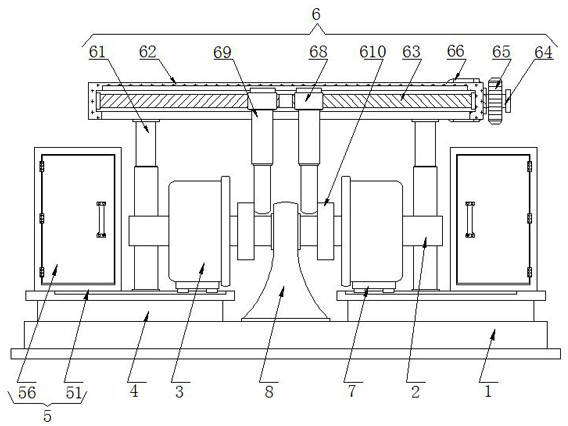
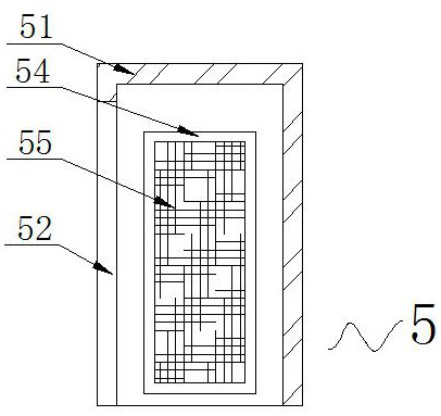
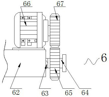
Embodiment Construction

[0027] The following will clearly and completely describe the technical solutions in the embodiments of the present invention with reference to the accompanying drawings in the embodiments of the present invention. Obviously, the described embodiments are only some, not all, embodiments of the present invention. Based on the embodiments of the present invention, all other embodiments obtained by persons of ordinary skill in the art without making creative efforts belong to the protection scope of the present invention.

[0028] see Figure 1-5, the embodiment of the present invention provides a technical solution: a device for dismantling the counter-wheel of the rotor of the induced draft fan. By placing the rotor shaft 2 with the counter-wheel 3 on the support frame 8, two second electric push rods 69 are used to drive the card The opposite push of the block 610 makes the counter wheel 3 move axially on the rotor shaft 2 until the counter wheel 3 is separated from the rotor ...


PUM


Abstract

The invention discloses a draught fan rotor and paired wheel disassembly device and relates to the technical field of draught fans. The draught fan rotor and paired wheel disassembly device comprisesa base, a rotor shaft, a pair of wheels slidably connected to the two sides of the surface of the rotor shaft and fixing tables fixedly connected to the two sides of the top of the base. A storage assembly is arranged on one side of the top of each fixing table. A disassembling assembly is arranged on the other side of the top of each fixing table. Each disassembling assembly comprises a first electric push rod and a fixing frame, and the bottom end of each first electric push rod is fixedly connected with one side of the top of the corresponding fixing table. According to the draught fan rotor and paired wheel disassembly device, the rotor shaft with the pair of wheels is placed on a support frame, and two second electric push rods drive clamping blocks to move away from each other so asto enable the pair of wheels to move on the rotor shaft in the axial direction until the pair of wheels is disengaged from the rotor shaft. By the adoption of the disassembly device, convenient disassembly of the pair of wheels and the rotor shaft is achieved, no manual disassembly is needed, the operation is convenient, the disassembly efficiency is high, and certain potential safety hazards arereduced.

Description

technical field [0001] The invention relates to the technical field of induced draft fans, in particular to a device for disassembling rotor-to-wheels of induced draft fans. Background technique [0002] The induced draft fan is a device that generates negative pressure through the rotation of the impeller and then extracts air from the system (equipment). It is generally installed at the end of the boiler to extract the hot flue gas in the furnace. , Different ways of negative pressure use are divided into induced draft fans (negative pressure use) and blowers (positive pressure use), induced draft fans are widely used in factories, mines, tunnels, cooling towers, vehicles, ships and buildings for ventilation, dust removal and cooling ; Ventilation and induction of boilers and industrial furnaces; cooling and ventilation in air-conditioning equipment and household electrical appliances; drying and selection of grain; wind tunnel wind source and inflation and propulsion of h...

Claims


Application Information

Patent Timeline
Patent Type & Authority Applications(China)
IPC IPC(8): B23P19/00
CPCB23P19/00
Inventor 冯宏涛蔺荣德钱为马小林郑欣冉
Owner 华电呼图壁能源有限公司热电厂
Learn More