Gravity compensation device for step-by-step expansion type solar wing ground test

A ground test and gravity compensation technology, which is used in simulation devices for space navigation conditions, transportation and packaging, space navigation equipment, etc. It can solve the problems of easy jamming, difficult processing of long guide rails, and high requirements for guide rail processing and assembly and adjustment accuracy.

Active Publication Date: 2020-09-18
CHANGGUANG SATELLITE TECH CO LTD
View PDF8 Cites 7 Cited by
  • Summary
  • Abstract
  • Description
  • Claims
  • Application Information

AI Technical Summary

Problems solved by technology

[0004] In view of this, the present invention aims to propose a gravity compensation device for step-by-step deployment of solar wing ground tests, which solves various problems that may be encountered in the large-scale two-dimensional deployment of traditional technical solutions, and the present invention effectively solves In the case of large-scale two-dimensional deployment of traditional technical solutions, the problems of difficult processing of long guide rails, high requirements for guide rail processing and assembly accuracy, and easy jamming during deployment are solved. The present invention is easy to carry, and has good economy and applicability

Method used


Image

  • Gravity compensation device for step-by-step expansion type solar wing ground test
  • Gravity compensation device for step-by-step expansion type solar wing ground test
  • Gravity compensation device for step-by-step expansion type solar wing ground test

Examples


Embodiment Construction

[0031] It should be noted that, in the case of no conflict, the embodiments of the present invention and the features in the embodiments can be combined with each other.

[0032] The present invention will be described in detail below with reference to the accompanying drawings and examples.

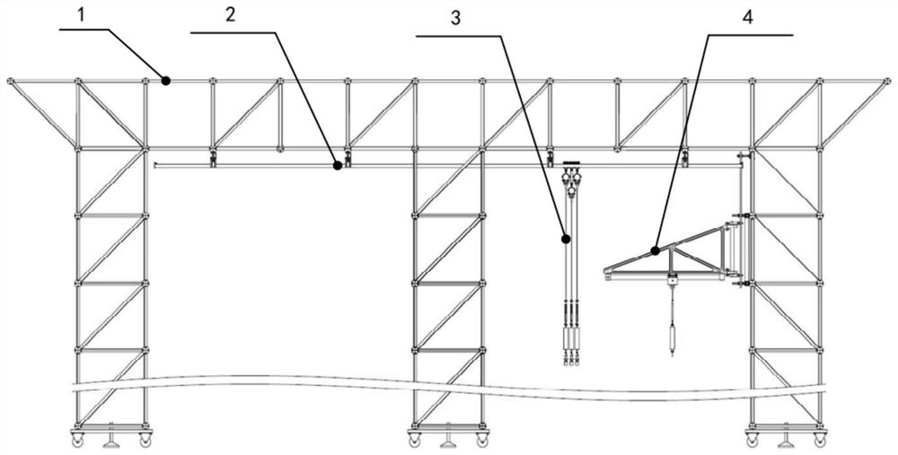
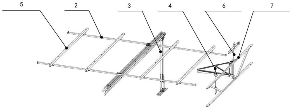
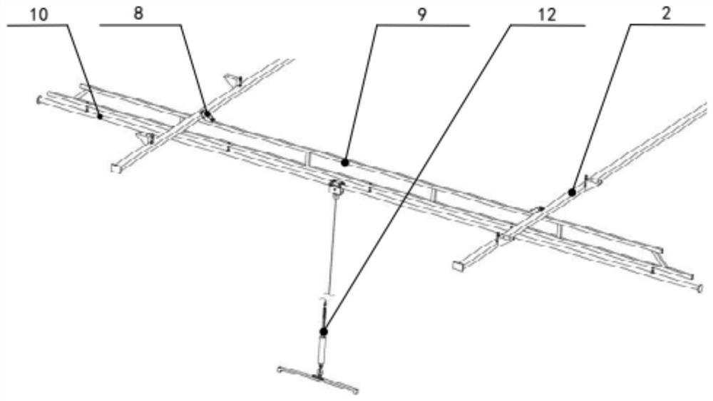
[0033] Such as Figure 1-Figure 7 As shown, a gravity compensation device for the step-by-step deployment solar wing ground test includes a truss 1, a transverse guide rail 2, a sliding mechanism 3 and a swing mechanism 4. The truss 1 is spliced ​​by aluminum alloy clubs, and the internal clearance About 5400mm in length, 4400mm in width and 4000mm in height, 4 universal wheels with brake function and 1 foot are installed at the bottom of each column; two sets of horizontal guide rails 2 are arranged, and are installed through several trusses arranged in parallel The bracket 5 is installed on the upper part of the truss 1, and the swing mechanism 4 is installed on the truss 1 through th...


PUM


Abstract

The invention provides a gravity compensation device for a step-by-step expansion type solar wing ground test. The device comprises trusses, two sets of transverse guide rails, a plurality of sets ofsliding mechanisms and a swing mechanism. The two sets of transverse guide rails are installed on the upper portions of the trusses through a plurality of truss installation supports, the swing mechanisms are installed on the trusses, the multiple sets of sliding mechanisms cooperate with the two sets of transverse guide rails, and the section of each transverse guide rail is rectangular; each setof sliding mechanism comprises two transverse sliding frames, a longitudinal shaft support and a longitudinal shaft, the upper portions of the transverse sliding frames are erected on the transverseguide rails on the corresponding sides respectively and slide along the transverse guide rails of the transverse sliding frames, the swing mechanism and each longitudinal shaft are provided with a suspension assembly respectively, and the suspension assemblies slide along the longitudinal shafts and the swing mechanism. Therefore, problems that a long guide rail in a traditional large-range two-dimensional unfolding mechanism is difficult to machine, the guide rail machining and adjusting precision requirements are high, and the unfolding process is prone to being jammed are effectively solved, and the device is convenient to carry and has good economical efficiency and applicability.

Description

technical field [0001] The invention belongs to the technical field of solar wing structure and mechanism ground tests, and in particular relates to a gravity compensation device for step-by-step deployment solar wing ground tests. Background technique [0002] In order to simulate the space microgravity environment during the test of the solar wing structure and mechanism products on the ground, it is necessary to compensate the product's own gravity to achieve zero gravity test conditions. Compared with synchronous deployment, step-by-step deployment of solar wings is more complicated and requires a larger deployment space. [0003] At present, there are three commonly used schemes for the gravity compensation device of the solar wing ground test: the air-floor support type, the air-floor suspension type, and the roller suspension type. The air-floating support type needs to be used with a marble platform. The test system is expensive to build and difficult to transport. ...

Claims


Application Information

Patent Timeline
Patent Type & Authority Applications(China)
IPC IPC(8): B64G7/00
CPCB64G7/00
Inventor 赵春娟谷松张道威孙洪雨张雷赵相禹
Owner CHANGGUANG SATELLITE TECH CO LTD
Why Eureka
Try Eureka