
Plastic pipe cutting and stacking machine

A technology of plastic tubes and stackers, which is applied in the stacking, metal processing, transportation and packaging of objects, can solve the problems of unsafe and inconvenient artificial stacking, and achieve the effect of reducing labor costs.

Inactive Publication Date: 2020-09-18
福州经济技术开发区千金诺智能科技有限公司
View PDF0 Cites 2 Cited by
  • Summary
  • Abstract
  • Description
  • Claims
  • Application Information

AI Technical Summary

Problems solved by technology

[0002] Plastic pipe cutting is a relatively important part of plastic pipe processing. It should be considered whether the chainsaw needs to have the function of storing, and then the cut products need to be stacked, but artificial stacking is neither safe nor convenient, so the machine automatically Stacking can solve this problem, but in mechanical automatic stacking, it should be considered that the stacking platform needs to move up and down with the number of stacked layers, so it is necessary to design a mechanical solution to related problems

Method used


Image

  • Plastic pipe cutting and stacking machine
  • Plastic pipe cutting and stacking machine
  • Plastic pipe cutting and stacking machine

Examples


Embodiment Construction

[0018] Combine below Figure 1-9 The present invention is described in detail, and for convenience of description, the orientations mentioned below are now stipulated as follows: figure 1 The up, down, left, right, front and back directions of the projection relationship itself are consistent.

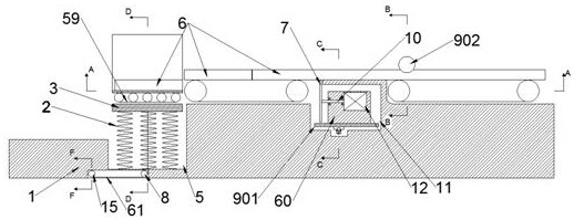
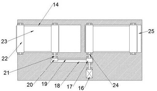
[0019] refer to Figure 1-9 , according to an embodiment of the present invention, a plastic pipe cutting and stacking machine includes a fuselage 1 and a conveying chamber 49 with an upward opening on the left side of the top wall of the fuselage 1, and an opening is provided in the bottom wall of the conveying chamber 49 The upward stacking cavity 5 communicates with the transfer cavity 49, twelve compression springs 2 are evenly fixed on the bottom wall of the stacking cavity 5, and one end of the compression springs 2 away from the bottom wall of the stacking cavity 5 is fixedly arranged with Stacking plate 3, the center of the bottom wall of the stacking plate 3 is fixed with a ...


PUM


Abstract

The invention discloses a plastic pipe cutting and stacking machine comprising a machine body and a conveying cavity with an upward opening arranged on the left side of the top wall of the machine body; a stacking cavity with an upward opening is arranged in the bottom wall of the conveying cavity and communicates with the conveying cavity; twelve compression springs are uniformly and fixedly arranged on the bottom wall of the stacking cavity; a stacking plate is fixedly arranged at the end, far away from the bottom wall of the stacking cavity, of each compression spring; a pull wire is fixedly arranged at the center of the bottom wall of the stacking plate; an opening at the center of the bottom wall of the stacking cavity communicates with a deceleration cavity in the lower side; and a first rotating shaft which extends forwards and backwards is rotatably arranged on the right side of the deceleration cavity. According to the plastic pipe cutting and stacking machine, an elastic potential energy formula of springs is adopted, the gravities of each layer of plastic pipes are superimposed to enable a stacking platform to fall the same height each time, so that the next layer of plastic pipes can be conveniently stacked; the stacking platform rises slowly after the plastic pipes are transferred through elastic potential energy of torsion springs; an electric saw is enabled to lift to cut the plastic pipes through a screw slide block structure; the plastic pipe cutting and stacking machine is relatively safe; and manpower is reduced.

Description

technical field [0001] The invention relates to the technical field of plastic pipe processing, in particular to a plastic pipe cutting and stacking machine. Background technique [0002] Plastic pipe cutting is a relatively important part of plastic pipe processing. It should be considered whether the chainsaw needs to have the function of storing, and then the cut products need to be stacked, but artificial stacking is neither safe nor convenient, so the machine automatically Stacking can solve this problem, but in mechanical automatic stacking, it should be considered that the stacking platform needs to move up and down with the number of stacked layers, so it is necessary to design a machine to solve related problems. Contents of the invention [0003] The object of the present invention is to provide a plastic pipe cutting and stacking machine for overcoming the above-mentioned defects in the prior art. [0004] A cutting and stacking machine for plastic pipes accord...

Claims


Application Information

Patent Timeline
Patent Type & Authority Applications(China)
IPC IPC(8): B65G57/03B26D7/32B26D1/14B26D1/143
CPCB26D1/14B26D1/143B26D7/32B65G57/035
Inventor 李柳柳
Owner 福州经济技术开发区千金诺智能科技有限公司
Learn More