Paying off device for building construction site and using method thereof
A technology of construction site and pay-off device, which is applied in the directions of cleaning methods using tools, cleaning methods and utensils, chemical instruments and methods, etc., can solve problems such as increasing the use cost, spending a lot of time, measuring wire winding, etc., and achieve the cost of use. Low, save time, improve smooth effect
- Summary
- Abstract
- Description
- Claims
- Application Information
AI Technical Summary
Problems solved by technology
Method used
Image
Examples
Embodiment 1
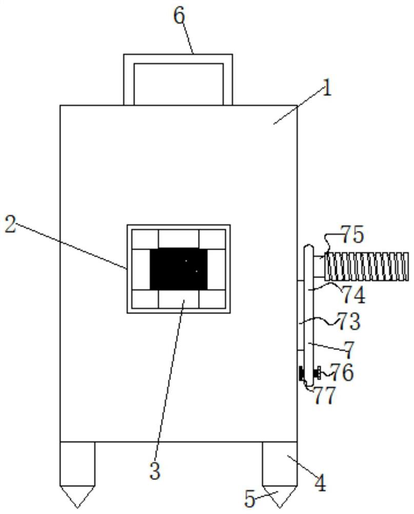
[0027] Such as figure 1 shown;
[0028] A wire pay-off device for a house construction site, comprising a housing 1, legs 4 installed around the bottom of the housing 1 for support, and a take-up wheel 9 placed inside the housing 1 for winding the wire. The front of the housing 1 is connected with a pay-off pipe 2, the top of the housing 1 is bolted with a handle 6, a rotating assembly 7 is installed on one side of the housing 1 and inside, and the top of the inner cavity of the housing 1 is installed with an auxiliary take-up wheel. 9 Auxiliary components 8 for take-up.
[0029] In the scheme of this embodiment: this embodiment 1 is the main structure of the pay-off device, and a handle 6 is installed on the top of the housing 1 for more convenience when carrying, and the bottom of the leg 4 is welded to make the release The line device uses a more stable cone block 5, which is used to fix the housing 1 conveniently when the line device is in use, thereby improving the stab...
Embodiment 2
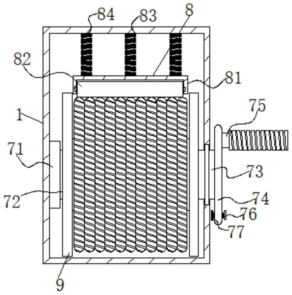
[0032] Such as figure 2 shown;
[0033] In combination with the content of Embodiment 1, the rotating assembly 7 includes a bearing 71 embedded in the inner wall of the housing 1, a connecting column 72 sleeved inside the bearing 71 and bolted to the take-up wheel 9, and another bolted to the take-up wheel 9. The mounting column 73 on the side, the other end of the mounting column 73 penetrates to one side of the housing 1 and is socketed with the turntable 74, the surface of the mounting column 73 is sleeved with a rotating shaft embedded in the inner side wall of the housing 1, the other A handle 75 is welded on the side, and the surface of the rotating disk 74 is threadedly connected with a limit bolt 76 under the handle 75, and the threaded end of the limit bolt 76 is welded with a limit block 77.
[0034] In the scheme of this embodiment: as the first carrier rotation method of this embodiment 1, when the rotating assembly 7 is in use, the user can rotate the handle 75,...
Embodiment 3
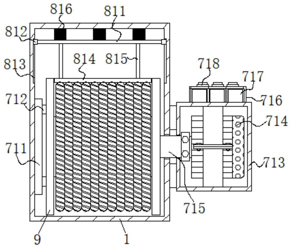
[0036] Such as image 3 shown;
[0037] In combination with the content of Embodiment 1, the rotating assembly 7 also includes a circular slide rail 711 and two sliders 1 712 that are slidably connected to the circular slide rail 711 and bolted to one side of the take-up wheel 9 and are installed on the shell through a connecting piece. The protective shell 713 on one side of the body 1, the inner cavity of the protective shell 713 is bolted with a positive and negative motor 714 through a connector, the output end of the positive and negative motor 714 is sleeved with a rotating shaft 715 through a coupling, and the other end of the rotating shaft 715 It penetrates to the inner cavity of the housing 1 and is bolted to the take-up pulley 9, and one side of the housing 1 is provided with a through groove used in conjunction with the rotating shaft 715, and the top of the protective shell 713 is bolted to a housing 716, and the inside of the housing 716 is placed There is an ac...
PUM
 Abstract
Description
Claims
Application Information
 - R&D
- Intellectual Property
- Life Sciences
- Materials
- Tech Scout
- Unparalleled Data Quality
- Higher Quality Content
- 60% Fewer Hallucinations
Browse by: Latest US Patents, China's latest patents, Technical Efficacy Thesaurus, Application Domain, Technology Topic, Popular Technical Reports.
© 2025 PatSnap. All rights reserved.Legal|Privacy policy|Modern Slavery Act Transparency Statement|Sitemap|About US| Contact US: help@patsnap.com


