
Functionally graded deformation joint structure and manufacturing method

A technology of functional gradient and deformation joints, which is applied in the direction of building structure and construction, to achieve the effect of improving overall performance, reducing cost, and enhancing overall functionality

Pending Publication Date: 2020-09-18
HEFEI UNIV OF TECH
View PDF0 Cites 0 Cited by
  • Summary
  • Abstract
  • Description
  • Claims
  • Application Information

AI Technical Summary

Problems solved by technology

[0005] In order to solve the waterproof problem of deformation joints, the present invention provides a functional gradient deformation joint structure and manufacturing method

Method used


Image

  • Functionally graded deformation joint structure and manufacturing method
  • Functionally graded deformation joint structure and manufacturing method

Examples


Embodiment 1

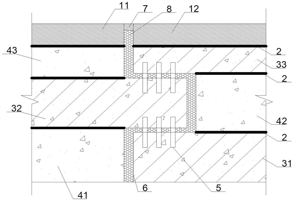
[0045] like Figure 1-2 As shown, a functional gradient deformation seam structure, the deformation seam is a tongue-and-groove seam 6, which can maximize the waterproof ability of the deformation seam in terms of structural design. Set different concrete layers in different thickness directions on both sides of the groove joint 6 to construct a functional gradient concrete layer. A sealing material 7 is arranged in the tongue and groove seam 6 . The high impermeability and anti-cracking concrete layers on the left and right sides of the groove 6 are the first high-impermeability and anti-cracking concrete layer 11 and the second high impermeability and anti-cracking concrete layer 12 respectively.

[0046] The first ordinary concrete layer 41 is located on the concave surface of the grooved joint 6, and the second ultra-high toughness concrete layer 32 is placed on the convex surface, and the upper and lower adjacent layers of the second ordinary concrete layer 42 are both u...

Embodiment 2

[0055] The concrete steps of making the functional gradient deformation joint structure of embodiment 1 are as follows:

[0056] S1. Pouring the first ordinary concrete layer 41 at the bottom of the left side and the first ultra-high toughness concrete layer 31 at the bottom of the right side, and reserving 5 holes for connectors on the formwork for pouring the first ultra-high toughness concrete layer 31;

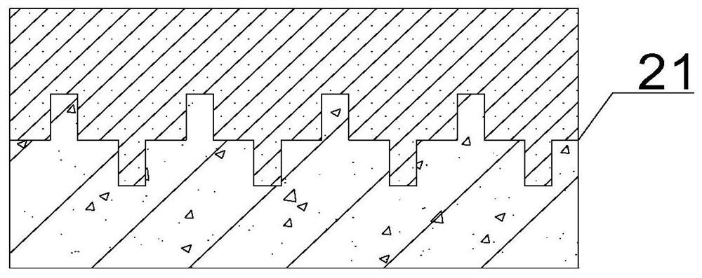
[0057] S2. The upper surface of the left and right sides of the soil layer and the lower surface of the formwork of the concrete layer to be poured are subjected to interface strengthening treatment;

[0058] S3, respectively pouring the second ultra-high toughness concrete layer 32 on the first ordinary concrete layer 41 and pouring the second ordinary concrete layer 42 on the first ultra-high toughness concrete layer 31, when pouring the second ultra-high toughness concrete layer 32, A connecting piece 5 is arranged inside it;

[0059] S4. Perform interface strengthenin...


PUM

PropertyMeasurementUnit
particle sizeaaaaaaaaaa
tensile strengthaaaaaaaaaa
lengthaaaaaaaaaa

Abstract

The invention belongs to the field of civil engineering, and particularly relates to a functionally graded deformation joint structure and a manufacturing method. The deformation joint is a tongue-and-groove joint, different concrete layers are arranged on the two sides of the tongue-and-groove joint in different thickness directions to construct a functionally graded concrete layer, the portion,close to an upstream face concrete layer, of the functionally graded concrete layer is a high-impermeability anti-crack concrete layer, and a sealing material is arranged in the portion, at the high-impermeability anti-crack concrete layer, of the tongue-and-groove joint. The functionally graded deformation joint structure has the advantages that a tongue-and-groove joint is better in waterproof performance compared with a common flat joint, but the integrity of concrete structures protruding out of the two sides of the tongue-and-groove joint is weak, under the influence of earthquakes or other factors, the tongue-and-groove joint is prone to breakage and deformation joint blockage, for the functionally graded deformation joint structure, the functionally gradient concrete layer is constructed on the two sides of the tongue-and-groove joint, and the upstream face of the tongue-and-groove joint is sealed by adopting the sealing material, so that the waterproofness is better realized under the condition of ensuring the strength.

Description

technical field [0001] The invention belongs to the field of civil engineering, and in particular relates to a functional gradient deformation joint structure and a manufacturing method. Background technique [0002] Due to factors such as temperature changes, uneven foundation settlement, and earthquakes, additional stress will be generated inside the building structure. This stress will cause cracks and damage to the building, greatly affecting its durability and safety. In order to reduce this effect, usually Deformation joints are reserved during design, and deformation joints can be divided into three types: expansion joints, settlement joints and shockproof joints. [0003] The problem of waterproofing has always been the focus and difficulty of setting deformation joints. If it is not handled properly, it will greatly reduce the durability of the structure, bring harm to the project, and cause direct or indirect economic losses. [0004] Due to its own defects, the t...

Claims


Application Information

Patent Timeline
Patent Type & Authority Applications(China)
IPC IPC(8): E04B1/682C04B28/04
CPCC04B28/04C04B2111/00612E04B1/6801E04B1/6806C04B14/06C04B18/08C04B18/146C04B14/48C04B2103/302
Inventor 丁兆东彭博王林白柱王静峰刘广
Owner HEFEI UNIV OF TECH
Learn More