
Rotary cushion valve device, speed reducer and use method of speed reducer

A technology of slewing buffer and valve device, which is applied in the field of buffer valves, can solve the problems of large impact and instability of cranes, achieve the effects of improving slewing performance, optimizing the use feel, and avoiding slewing impact

Active Publication Date: 2020-09-18
XCMG XUZHOU TRUCK MOUNTED CRANE
View PDF4 Cites 3 Cited by
  • Summary
  • Abstract
  • Description
  • Claims
  • Application Information

AI Technical Summary

Problems solved by technology

This valve has no oil pressure buffer for the hydraulic oil entering the motor or returning oil from the motor or the brake oil flowing into the brake of the slewing reducer, which also results in that when the hydraulic oil enters the motor oil chamber or returns oil from the motor oil chamber or the brake oil returns , there is no limit to the hydraulic oil, the feedback to the slewing reducer brake is to open or close instantly, which will cause the output gear to start to rotate and stop to rotate instantly, thus affecting the impact of the crane during the start and stop of the slewing. The phenomenon

Method used


Image

  • Rotary cushion valve device, speed reducer and use method of speed reducer

Examples


Embodiment 1

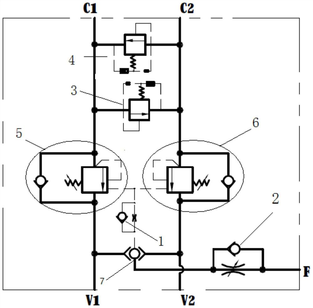
[0040] Such as figure 1 As shown, the rotary buffer valve device in the embodiment of the present invention includes:

[0041] The first oil circuit includes a connected first two-way balance valve 5 and a first buffer relief valve 3, and the first buffer relief valve 3 is used to connect to a motor;

[0042] The second oil circuit includes a connected second two-way balance valve 6 and a second buffer relief valve 4, the second buffer relief valve 4 is used to connect the motor; the first buffer relief valve 3 and The second buffer overflow valve 4 is arranged in parallel, and the conduction directions of the two are opposite;

[0043] Adjustable one-way throttle valve 2, used to connect with the brake oil circuit;

[0044] Shuttle valve 7, its two ends are respectively connected with the oil ports of the first two-way balance valve 5 and the second two-way balance valve 6, and are connected with the oil ports of the adjustable one-way throttle valve 2;

[0045] The one-wa...

Embodiment 2

[0051] An embodiment of the present invention provides a reducer, including a rotary buffer valve device, a motor and a brake oil circuit;

[0052] The rotary buffer valve device includes:

[0053] The first oil circuit includes a connected first two-way balance valve 5 and a first buffer relief valve 3;

[0054] The second oil circuit includes a connected second two-way balance valve 6 and a second buffer relief valve 4;

[0055] Adjustable one-way throttle valve 2;

[0056] Shuttle valve 7, its two ends are respectively connected with the oil ports of the first two-way balance valve 5 and the second two-way balance valve 6, and are connected with the oil port of the adjustable one-way throttle valve 2;

[0057] A one-way throttle valve 1 is connected to the oil ports of the first two-way balance valve 5, the second two-way balance valve 6 and the shuttle valve 7 respectively;

[0058] The motor is connected to the first buffer relief valve 3 and the second buffer relief v...

Embodiment 3

[0068] An embodiment of the present invention provides a method for using a reducer, including the following steps:

[0069] Part of the hydraulic oil passes through the first two-way balance valve 5 and then reaches the first buffer relief valve. At this time, if the hydraulic oil pressure is greater than the set pressure of the first buffer relief valve 3, the first buffer relief valve starts to function and Release the pressure to stabilize the pressure, and then input the regulated hydraulic oil from the first buffer relief valve to the oil inlet of the motor;

[0070] Pass another part of the hydraulic oil through the shuttle valve 7 and flow through the adjustable one-way throttle valve 2. At this time, the adjustable one-way throttle valve 2 does not work, and the hydraulic oil is transferred from the brake oil of the adjustable one-way throttle valve 2. The outlet flows out, and the brake of the speed reducer connected to the brake oil circuit is opened, and the motor ...


PUM


Abstract

The invention discloses a rotary cushion valve device, a speed reducer and a use method of the speed reducer. The speed reducer and the rotary cushion valve device each comprises a first oil way, a second oil way, an adjustable one-way throttle valve, a shuttle valve and a one-way throttle valve, wherein the first oil way comprises a first two-way balance valve and a first cushion type overflow valve which are connected; the second oil way comprises a second two-way balance valve and a second buffer type overflow valve which are connected with each other; two ends of the shuttle valve are connected with oil ports of the first two-way balance valve and the second two-way balance valve, and are connected with an oil port of the adjustable one-way throttle valve; and the one-way throttle valve is connected with the oil ports of the first two-way balance valve, the second two-way balance valve and the shuttle valve. The whole rotation process is more stable, rotation impact of the rotationspeed reducer at the moment of starting and stopping of rotation operation is reduced, shaking is slowed down, and the operation hand feeling is improved.

Description

technical field [0001] The invention belongs to the technical field of buffer valves, and in particular relates to a rotary buffer valve device, a reducer and a use method thereof. Background technique [0002] With the continuous development of the construction machinery industry, the performance of the truck-mounted crane is also continuously improved, such as the length of the boom and the increase of the lifting weight. In the process of continuous development, there are also some problems in the actual market application process. For example, during the operation of the crane, when the user uses the operating handle to perform the rotary operation, when the user uses the operating handle to perform the rotary action, there will be a problem at a certain moment. Sudden rotation causes problems such as unstable rotation and uncomfortable operation. When the crane is about to stop the rotation, the handle is lowered, and the arm of the crane stops directly, causing serious...

Claims


Application Information

Patent Timeline
Patent Type & Authority Applications(China)
IPC IPC(8): F15B13/02F15B21/00
CPCF15B13/02F15B13/025F15B13/027F15B13/028F15B21/001F15B2211/528F15B2211/55F15B2211/75F15B2211/851F15B2211/853F15B2211/8606
Inventor 陈志伟孔德强商晓恒马磊里周哲奚浩孙新年
Owner XCMG XUZHOU TRUCK MOUNTED CRANE
Learn More