Worm steering type rotary speed reducer for multi-point drive tracking

A rotary reducer and multi-point drive technology, which is applied in the direction of electromechanical devices, mechanical equipment, electric components, etc., can solve problems such as difficulties, achieve cost savings, prevent external forces from pushing the solar tracking system, and improve the rigidity of the overall structure

Pending Publication Date: 2020-09-18
JIANGYIN HUAFANG NEW ENERGY HIGH TECH EQUIP
View PDF0 Cites 9 Cited by
  • Summary
  • Abstract
  • Description
  • Claims
  • Application Information

AI Technical Summary

Problems solved by technology

However, there are still some problems in the rotary reducer currently on the market in order to realize the function of multiple rotary synchronous parallel dr

Method used


Image

  • Worm steering type rotary speed reducer for multi-point drive tracking
  • Worm steering type rotary speed reducer for multi-point drive tracking
  • Worm steering type rotary speed reducer for multi-point drive tracking

Examples


Example Embodiment

[0042] The present invention will be described in further detail below in conjunction with the embodiments of the drawings.

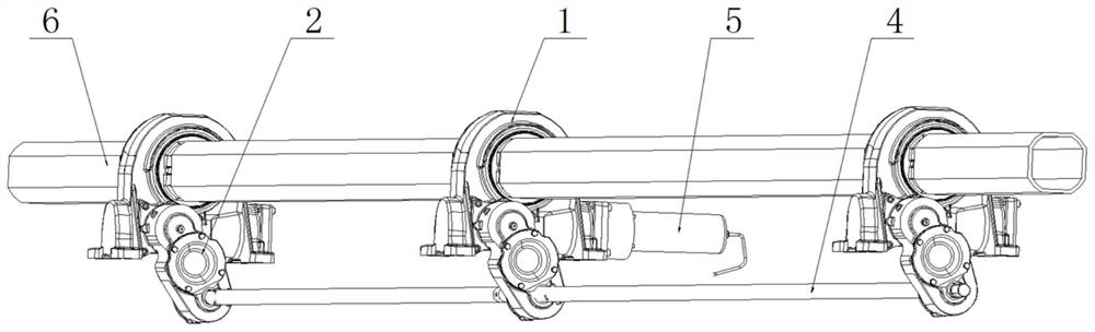
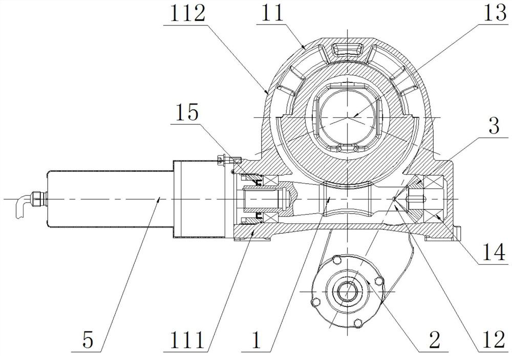
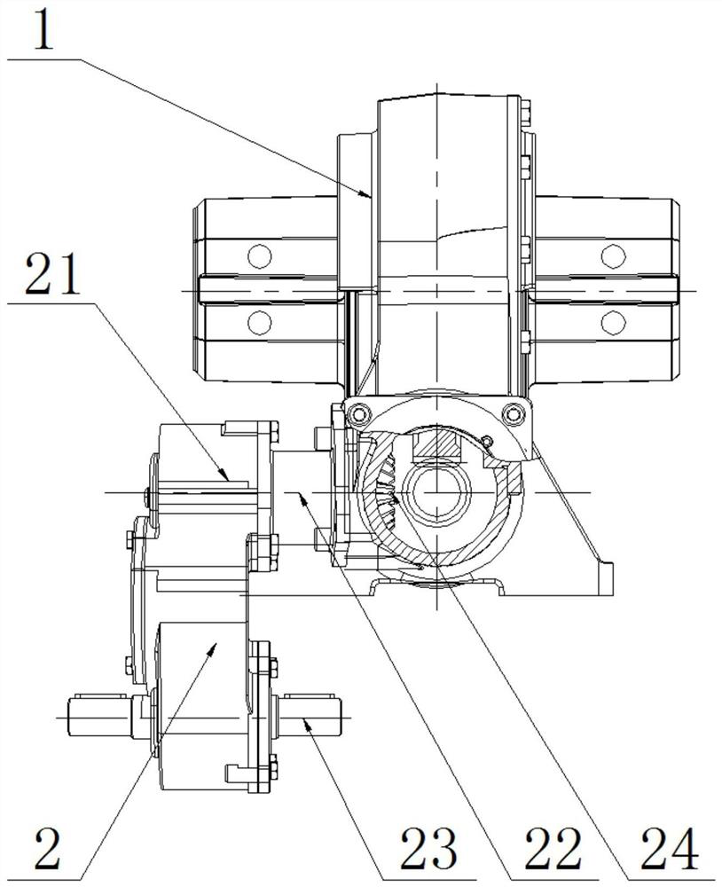
[0043] Such as Figure 1 ~ Figure 4 As shown, the worm-steering type multi-point drive tracking rotary reducer in this embodiment includes a plurality of worm-gear rotary drive devices 1 arranged at intervals in the front and rear. The worm-wheel rotary drive device 1 includes a base 11, The base 11 includes a shaft housing 111 and a seat ring 112. A worm 12 is provided in the shaft housing 111, and a gear shaft 13 is provided in the seat ring 112. The worm 12 meshes with the gear shaft 13 and is adjacent to The main beam 6 is arranged between the gear shafts 13 of the two worm gear slewing drive devices 1; the static self-locking of the worm 12 and the gear shaft 13 of the multiple worm gear slewing drive devices 1 can effectively prevent external forces from pushing the solar tracking system to avoid System equipment damage occurs;

[0044] A gear box 2 ...


PUM


Abstract

The invention relates to a worm steering type rotary speed reducer for multi-point drive tracking. The speed reducer comprises a plurality of worm and gear rotary driving devices (1) arranged front and back at intervals, wherein each worm and gear rotary driving device (1) comprises a base (11), each base (11) comprises a shaft shell (111) and a base ring (112), a worm (12) is arranged in each shaft shell (111), a gear shaft (13) is arranged in each base ring (112), the worms (12) mesh with the gear shafts (13), and a main beam (5) is arranged between the gear shafts (13) of every two adjacentworm and gear rotary driving devices (1). According to the speed reducer, a mode that the worm and gear rotary driving devices and gear boxes are used in combination is adopted, the gear boxes are driven to output transmission power through bevel gears installed on the worms, and parallel driving of the plurality of worm and gear rotary driving devices is achieved.

Description

technical field [0001] The invention relates to a worm-steering type multi-point drive tracking rotary reducer, which is mainly used in a solar photovoltaic tracking system, especially a solar flat single-axis multi-point parallel drive tracking system. Background technique [0002] At present, the most common application of solar photovoltaic tracking is the flat single-axis tracking system. In the flat single-axis tracking system, most of them still use the rotary reducer or electric push rod single-point drive, that is, a reducer or electric push rod single Point drives the rotation of the entire main shaft. This form is widely used at home and abroad. It is characterized by simple structure and easy installation. The disadvantage is that there is only one locking protection point at the drive position, which may easily cause damage to the drive or damage the drive when encountering strong winds. Twisted failure of the main beam tube. Recently, more and more tracking man...

Claims


Application Information

Patent Timeline
IPC IPC(8): F16H37/04F16H1/22F16H57/023F16H57/029F16H57/038F16H57/039H02K7/116H02S20/32
CPCF16H1/222F16H37/041F16H57/023F16H57/029F16H57/038F16H57/039F16H2057/02039F16H2057/0213H02K7/1166H02S20/32Y02E10/50
Inventor 潘苗夏飞
Owner JIANGYIN HUAFANG NEW ENERGY HIGH TECH EQUIP
Why Eureka
Try Eureka