Thick-wall part optical system with light incident collimation plane and cylindrical stripes

An optical system and cylindrical technology, applied in the field of optical systems for thick-walled parts, can solve the problems of reduced uniformity, poor uniformity, and defects in uniformity of thick-walled parts, so as to avoid waste of light energy efficiency, reduce waste of light energy efficiency, and improve The effect of energy efficiency uniformity

Pending Publication Date: 2020-09-18
MAGNETI MARELLI AUTOMOTIVE COMPONENTS WUHU
View PDF0 Cites 0 Cited by
  • Summary
  • Abstract
  • Description
  • Claims
  • Application Information

AI Technical Summary

Problems solved by technology

However, LED light energy is distributed in a Gaussian curve with the divergence angle of the light. The larger the divergence angle, the lower the light energy distribution. Based on the precision limit of the current manufacturing process, all thick-walled parts must leave a certain amount of inversion at the edge of the draft surface. Corner and draft angle, uneven distribution of light energy and chamfering will cause defects in the collimation system, resulting in obvious dark areas on the light-emitting surface corresponding to the position of the chamfering and draft angle, resulting in a decrease in the uniformity of thick-walled parts in the vertical direction phenomenon, the thickness of thick-walled parts is also greatly restricted due to the influence of uniformity in the vertical direction. For thick-walled parts with a thickness exceeding 8mm, there will be defects in the uniformity in the vertical direction, and the greater the thickness, the greater the uniformity. Poor, the thickness of the current thick-walled parts is basically less than 10mm. However, with the new trend of OEMs to complicate the shape and function of automobile lights, the thickness of the existing thick-walled parts can no longer be satisfied, which also brings uniformity. question

Method used


Image

  • Thick-wall part optical system with light incident collimation plane and cylindrical stripes
  • Thick-wall part optical system with light incident collimation plane and cylindrical stripes
  • Thick-wall part optical system with light incident collimation plane and cylindrical stripes

Examples


Embodiment Construction

[0030] In order to deepen the understanding of the present invention, the present invention will be further described in detail below in conjunction with examples, which are only used to explain the present invention, and do not constitute a limitation to the protection scope of the present invention.

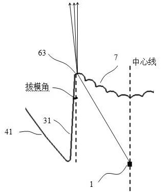
[0031] Image 6 Shown is a partial cross-sectional view of the light-incident surface of the optical system of a thick-walled part in existing applications. The light source 1 is located at the focal point. The angled inclined surface 31 is reflected by the left side wall 41 and then reaches the front light-emitting surface 5, and there is a dark area on the left side of the front light-emitting surface 5 shown in the figure; similarly, the light emitted by the light source 1 is collimated by the incident light collimation surface 2 To the front light-emitting surface 5, and after passing through the right draft angle inclined surface 32 and then reflected by the right side wal...


PUM

PropertyMeasurementUnit
widthaaaaaaaaaa

Abstract

The invention provides a thick-wall part optical system with a light incident collimation plane and cylindrical stripes. The thick-wall part optical system comprises a light source and a thick-wall part; the thick-wall part is provided with a light incident collimation plane, a left draft angle inclined surface, a right draft angle inclined surface, a left side wall, a right side wall, a front light-emitting surface, a chamfer I, a chamfer II, a chamfer III, a chamfer IV and a hole digging optical surface; the cylindrical stripes are arranged on the light incident collimation surface; light emitted by a light source at a focus is emitted from the front light-emitting face after the light-emitting direction is adjusted through the cylindrical stripes on the light-incident collimation face and the light is diffused, the dark space problem caused by chamfers and draft angles due to precision limitation of the manufacturing and machining process is solved, the uniformity of the thick-wallpart in the vertical direction is improved, and then the thick-wall part with a thicker shape can be designed. The uniformity of the thick-wall part in the horizontal direction can be improved throughthe cylindrical stripes on the optical surface of a dug hole; meanwhile, the light energy distribution of the central area and the light energy distribution of two sides tend to be consistent, the optical uniformity of the system is improved, and unnecessary light energy efficiency waste is reduced on the premise of meeting laws and regulations.

Description

technical field [0001] The invention relates to the technical field of automobile lighting, in particular to an optical system of thick-walled parts with cylindrical stripes added to the incident light collimating surface. Background technique [0002] Thick-walled parts are a new technology that puts the light source at the focal point to emit light, and the light is collimated through the thick-walled area, and then diffused through the front surface stripes to achieve a uniform display effect. It is widely used in civilian high-end cars, headlights, There are all rear lights, which are mostly used for turn signals, daytime running lights, position lights, brake lights, etc., mainly using LED light sources, which have gradually become the main configuration of car lights. [0003] With the trend of car lights, the diversity of shapes is becoming more and more important in the field of car lights, and the application of thick-walled parts in car lights will become more and ...

Claims


Application Information

Patent Timeline
Patent Type & Authority Applications(China)
IPC IPC(8): F21S43/20F21W103/10F21W103/35F21W103/55F21W103/45F21W103/20F21W107/10F21Y115/10
CPCF21Y2115/10F21S43/20F21W2103/10F21W2103/20F21W2103/35F21W2103/45F21W2103/55F21W2107/10
Inventor 楼木
Owner MAGNETI MARELLI AUTOMOTIVE COMPONENTS WUHU
Why Eureka
Try Eureka