
Building material strength detection device

A technology for strength detection and building materials, applied in measuring devices, using stable tension/pressure to test material strength, analyzing materials, etc., can solve the problem of unable to realize the storage of samples after automatic push detection and automatic replacement of samples continuously Detection, low detection efficiency and other problems, to achieve the effect of saving labor costs, realizing automatic feeding, and improving efficiency

Pending Publication Date: 2020-09-18
CHONGQING VOCATIONAL INST OF ENG
View PDF22 Cites 4 Cited by
  • Summary
  • Abstract
  • Description
  • Claims
  • Application Information

AI Technical Summary

Problems solved by technology

[0004] However, in the process of testing each sample, it is necessary to manually place each sample under the pressure testing machine for testing. After the previous sample is tested, the sample needs to be taken out from the bottom of the pressure testing machine, and then replaced with the next one. Samples are tested, that is, in the prior art, it is not possible to automatically replace samples for continuous testing, and at the same time, it is also impossible to automatically push the tested samples to a designated location for storage, which will lead to low overall testing efficiency and high labor costs

Method used

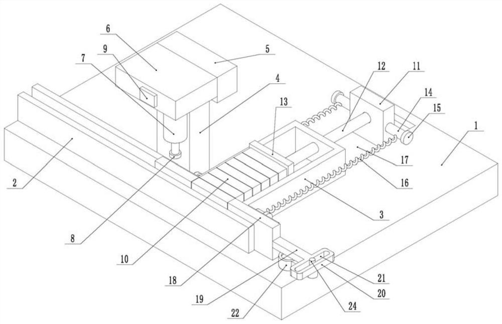

Image

  • Building material strength detection device
  • Building material strength detection device
  • Building material strength detection device

Examples


Embodiment 1

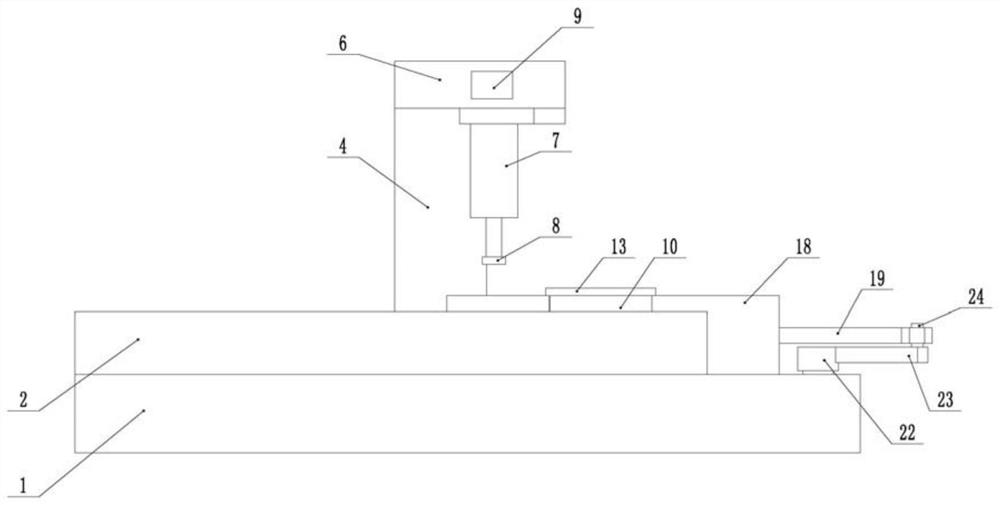
[0035] The embodiment is basically as attached figure 1 Shown: a device for testing the strength of building materials, including a support plate 1 having a rectangular parallelepiped structure, and a detection unit for detecting a sample 10 is provided on the support plate 1 .

[0036] Two guide plates 2 arranged parallel to each other are connected to the support plate 1, and a moving channel is formed between the two guide plates 2. In this embodiment, the two guide plates 2 are welded and fixed with the support plate 1, and the two guide plates 2 The distance between them is 1 cm larger than the width of the sample 10, so that the sample 10 can slide smoothly in the moving channel, and at the same time, the distance between the guide plate 2 and the sample 10 is small, and the sample 10 is not easy to be deflected.

[0037]The support plate 1 is also provided with a storage frame 3 vertically arranged with the guide plate 2, the storage frame 3 is a rectangular frame struc...

Embodiment 2

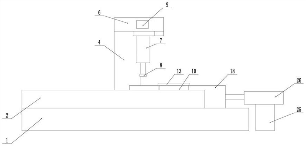
[0048] Such as image 3 As shown, a building material strength detection device differs from Embodiment 1 in that the drive unit in this embodiment includes a cylinder 26, the right side of the support plate 1 is provided with a support 25, and the cylinder body of the cylinder 26 and the support The seat 25 is fixedly connected by bolts, and the output shaft of the cylinder 26 is fixedly connected with the slide plate 18 .

[0049] When in use, the telescopic movement of the output shaft of the drive cylinder 26 drives the reciprocating sliding motion of the slide plate 18, and then the slide plate 18 pushes the sample 10 in the moving channel to the detection unit for detection. The structure in this embodiment is simple and easy to install .

Embodiment 3

[0051] A building material strength detection device, the difference from Embodiment 1 is that in this embodiment, the motor is electrically connected with a time relay (not shown in the figure).

[0052] In this embodiment, the setting of the time relay can control the delayed rotation of the motor. When the slide plate 18 pushes the sample 10 to the detection unit for detection, the time for delaying the reverse rotation of the motor is controlled by setting the time relay in advance. In this embodiment, the motor The time for delaying the reverse rotation is greater than the time for the detection unit to detect the sample 10. When the detection unit finishes detecting the sample 10, the output shaft of the hydraulic cylinder 7 moves upward to make the test head 8 away from the sample 10, and the motor rotates in reverse, thereby Returning the slide plate 18 to the initial position prepares for pushing the sample 10 to the detection unit next time. Such an arrangement can k...


PUM


Abstract

The invention relates to the field of building material detection. The invention discloses a building material strength detection device. The device comprises a support plate, and a detection unit fordetecting a sample is arranged on the support plate. The support plate is connected with two guide plates which are arranged in parallel, and a moving channel is formed between the two guide plates.A storage frame perpendicular to the guide plates is arranged on the support plate, one end of the storage frame is communicated with the moving channel, a sliding plate for pushing a sample to the detection unit is arranged in the moving channel in a sliding fit mode, and a driving unit for driving the sliding plate to slide in a reciprocating mode is arranged on one side of the sliding plate. Asliding block is arranged on the support plate in a sliding fit mode in the direction perpendicular to the guide plates, a tension spring is fixedly connected between the sliding block and the storageframe, a pushing rod is perpendicularly connected to the sliding block, and the end, away from the sliding block, of the pushing rod perpendicularly penetrates into the storage frame. According to the invention, a sample can be automatically pushed below the detection unit for detection, so that the detection efficiency is improved.

Description

technical field [0001] The invention relates to the field of building material detection, in particular to a building material strength detection device. Background technique [0002] Building materials can be divided into structural materials, decorative materials and some special materials, among which structural building materials include wood, bamboo, stone, cement, concrete, metal, bricks, ceramics, glass, engineering plastics, composite materials, etc. No matter what kind of structural building materials, they need to complete a series of quality inspections before they are put into use, including strength testing of building materials, and strength testing requires the use of specific strength testing equipment. [0003] At present, in the quality inspection of building materials, for the inspection of concrete strength inspection and mortar strength inspection, the method of laboratory inspection is mostly used for inspection. Taking the concrete strength test as an...

Claims


Application Information

Patent Timeline
Patent Type & Authority Applications(China)
IPC IPC(8): G01N3/12G01N3/02
CPCG01N3/12G01N3/02G01N2203/0019G01N2203/0048
Inventor 季敏季云皇甫双娥蒋博林李红立陈淑珍
Owner CHONGQING VOCATIONAL INST OF ENG
Learn More