Semi-submersible microscope objective with protective element and use of the same in multiphoton imaging method

A microscope objective, semi-submersible technology, applied in microscopes, optical components, microlithography exposure equipment, etc., can solve the problem of unusable microscope objective

Active Publication Date: 2020-09-18
3M INNOVATIVE PROPERTIES CO
View PDF14 Cites 0 Cited by
  • Summary
  • Abstract
  • Description
  • Claims
  • Application Information

AI Technical Summary

Problems solved by technology

If this happens, there is a possibility that expensive microscope objectives will become unusable

Method used


Image

  • Semi-submersible microscope objective with protective element and use of the same in multiphoton imaging method
  • Semi-submersible microscope objective with protective element and use of the same in multiphoton imaging method
  • Semi-submersible microscope objective with protective element and use of the same in multiphoton imaging method

Examples


Embodiment approach

[0056] In a first embodiment, the present invention provides a semi-submersible microscope objective, comprising:

[0057] Microscope objectives, including:

[0058] a protective cylinder having an optical entrance and an optical exit; and at least one optical element disposed within the protective cylinder and along an optical path extending between the optical entrance and the optical exit; and

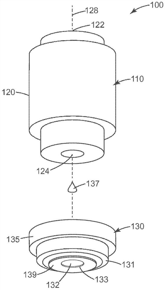
[0059] A protective element, which is attached to the microscope objective, seals the optical outlet but not the optical entrance, wherein the transparent portion of the protective element is aligned with the light path, and wherein the protective element can be separated from the microscope objective without damaging the microscope objective.

[0060] In a second embodiment, the present invention provides the semi-submersible microscope objective according to the first embodiment, wherein the protective element mechanically engages the microscope objective.

[0061] In a third emb...

Embodiment 1

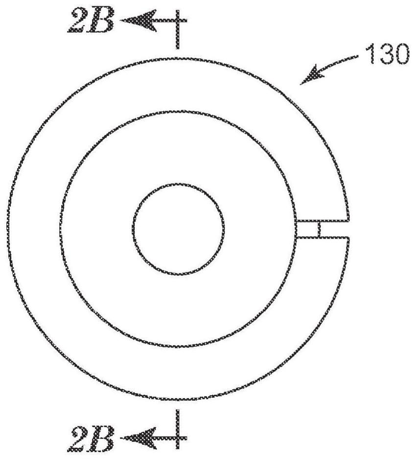
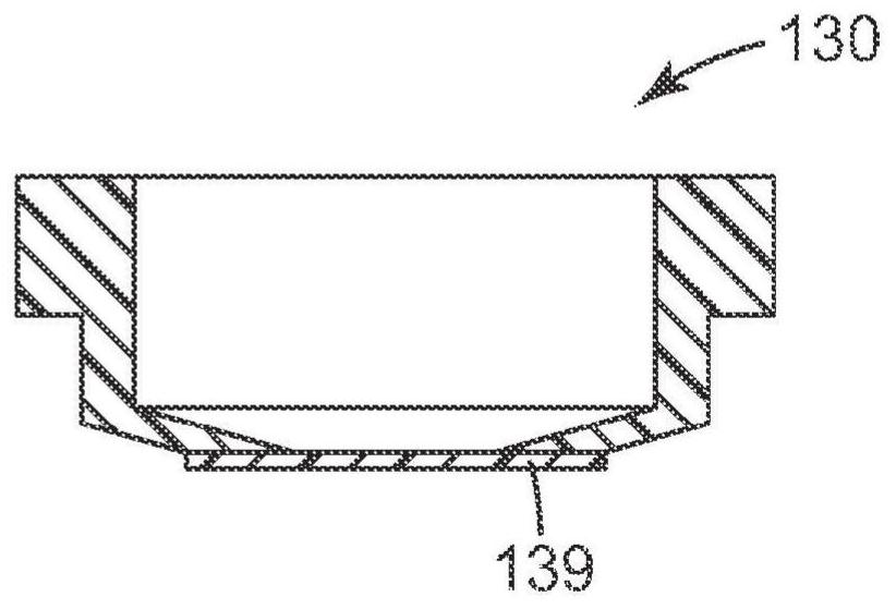
[0085] In this example, a microscope coverslip (approximately 170 to 190 microns) was glued to a protective element made of Delrin, which was clamped directly to a Zeiss 40x / 1.0 oil iris microscope objective (available at On protective tubes from Carl Zeiss Microscopy, LLC, Thornwood, New York, when used for multiphoton imaging and typically in figure 1 As shown in , the objective has a tapered end with a centrally positioned lens corresponding to the optical exit. The protection element is in Figures 2A-2C shown in . The protective element was then positioned so that the cover glass touched the lens at the optical exit, and a drop of Zeiss IMMERSOL 518F immersion lens oil was added between the lens surface and the cover glass to eliminate air.

[0086] Several structures were fabricated using semi-submersible microscope objectives made from liquid photoresists of various compositions. Figure 4 Scanning electron micrographs showing some simple geometries stacked on the z-...

Embodiment 2

[0091] An oil immersion microscope objective (4OX magnification, NA = 1.0, available from Carl Zeiss Microscopy, LLC) was coated with a thin layer of polyvinyl alcohol (PVA). A 10% by weight solution of PVA in water (6,000 g / mole, 80% hydrolyzed, Cat. No. 22225 from Polysciences, Inc., Warrington, Pennsylvania) was applied to the exposed lens and the surrounding metal at the immersion end of the microscope objective. Adjust the microscope objective so that excess solution flows off the final lens surface to provide a suitably thin clear protective coating. Place the coated microscope objective in an oven at 50 °C for 2 minutes to facilitate drying.

[0092] The coated end of the resulting semi-submersible microscope objective was dipped into the liquid photoresist that had been coated on the silicon substrate. The photoresist formulation consisted of 35 parts by weight of EPON 828 bisphenol A diglycidyl ether available from Momentive, Houston, Texas; 30 parts by weight of ER...


PUM


Abstract

The invention relates to a semi-submersible microscope objective with a protective element and uses of the same in a multiphoton imaging method, and provides a semi-submersible microscope objective (100). The semi-submersible microscope objective includes a microscope objective having a protective barrel (120) with an optical inlet (122) and optical outlet (124), and a protective element (130) affixed to the microscope objective, sealing the optical outlet (124) but not the optical inlet (122). A transparent portion (132) of the protective element is aligned with the optical exit (124). The protective element is separable from the microscope objective without damaging the microscope objective. Use of the semi- submersible microscope objective in a multiphoton imaging method is also disclosed.

Description

[0001] This application is an invention patent application No. 201480066005.2 that entered the Chinese national phase with the application date of December 1, 2014 and the title of the invention is "Semisubmersible Microscope Objective Lens with Protective Elements and Use of Objective Lens in Multiphoton Imaging Method" Divisional application. technical field [0002] Broadly, the present invention relates to microscope objectives and their use in multiphoton imaging methods. Background technique [0003] In a microscope, an objective lens (sometimes also called an objective lens in the art) is an optical element that gathers light from the object under observation and focuses it to create a real image. For example, the objective lens of a microscope is the one with the bottom closest to the sample. Simply put, a microscope objective is a high-magnification magnifying glass with a very short focal length. This is in close proximity to the sample being examined so that the...

Claims


Application Information

Patent Timeline
Patent Type & Authority Applications(China)
IPC IPC(8): G02B21/02G03F7/32G03F7/20G03F7/00G02B21/33G02B7/02G02B1/14G02B1/04
CPCG02B21/02G02B2207/114G02B21/33G03F7/70983G02B1/14G02B1/04G02B7/02G03F7/0005G03F7/2053G03F7/32
Inventor 布拉因·J·盖茨罗伯特·J·德沃李子成布拉德福德·B·怀特
Owner 3M INNOVATIVE PROPERTIES CO
Why Eureka
Try Eureka