Light field modulator and modulation method thereof

A modulator and beam technology, applied in the optical field, can solve the problems of unfavorable module application promotion and popularization, the module volume becomes larger, and the module assembly is inconvenient to adjust, so as to reduce distortion, improve window efficiency, and improve utilization rate. Effect

Active Publication Date: 2020-09-18
SHANGHAI NORTH OCEAN PHOTONICS CO LTD
View PDF6 Cites 2 Cited by
  • Summary
  • Abstract
  • Description
  • Claims
  • Application Information

AI Technical Summary

Problems solved by technology

[0003] However, since the amount of distortion of the illumination light area formed by different off-axis probe lights is different, in order to solve this problem, a complex optical system is often required in the prior art, generally requiring multiple independent optical elements, which will not only It will bring great inconvenience to the adjustment of the module, and it will also lead to the increase of the volume of the module and the increase of the cost, which is not conducive to the promotion and popularization of the application of the module.

Method used


Image

  • Light field modulator and modulation method thereof
  • Light field modulator and modulation method thereof
  • Light field modulator and modulation method thereof

Examples


Embodiment Construction

[0059] The following description serves to disclose the present invention to enable those skilled in the art to carry out the present invention. The preferred embodiments described below are only examples, and those skilled in the art can devise other obvious variations. The basic principles of the present invention defined in the following description can be applied to other embodiments, variations, improvements, equivalents and other technical solutions without departing from the spirit and scope of the present invention.

[0060] Those skilled in the art should understand that in the disclosure of the present invention, the terms "vertical", "transverse", "upper", "lower", "front", "rear", "left", "right", " The orientation or positional relationship indicated by "vertical", "horizontal", "top", "bottom", "inner", "outer", etc. is based on the orientation or positional relationship shown in the drawings, which are only for the convenience of describing the present invention...


PUM


Abstract

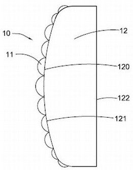
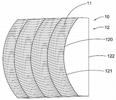
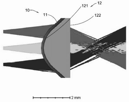
The invention discloses a light field modulator and a modulation method thereof. The light field modulator comprises at least one dodging element and a curved-surface light-transmitting substrate. Thecurved-surface light-transmitting substrate is provided with at least one curved surface; and the dodging element is correspondingly arranged on the curved surface of the curved-surface light-transmitting substrate, so that the microstructure of the dodging element is arranged along the curved surface of the curved-surface light-transmitting substrate and is used for homogenizing light emitted bya light source, and the light can uniformly and efficiently illuminate the corresponding target area; and the utilization rate of light energy is improved.

Description

technical field [0001] The invention relates to the field of optics, in particular to an optical field modulator and a modulation method thereof. Background technique [0002] In application scenarios such as lidar and TOF cameras, it is often necessary to illuminate the target of interest regionally. Once the target area of ​​interest is located outside the optical axis of the detection light source, problems such as distortion of the detection area, reduced energy utilization, and poor uniformity often occur. Specifically, distortion is a kind of off-axis aberration, which is a kind of aberration similar to the loss of object image caused by the change of vertical axis (ie lateral) magnification with the increase of field of view. In particular, the center direction of the probe light will be deflected at different angles if the off-axis value is different; in other words, the greater the off-axis value, the greater the angle at which the center direction of the probe l...

Claims


Application Information

Patent Timeline
Patent Type & Authority Applications(China)
IPC IPC(8): G02B27/09G02B27/00G02B3/00
CPCG02B27/0961G02B27/0927G02B27/0025G02B3/0037G01B11/22G02B3/005G02B3/0075G02B3/08G02B3/0006G02B27/0983
Inventor 孟玉凰黄河楼歆晔郑旭君林涛
Owner SHANGHAI NORTH OCEAN PHOTONICS CO LTD
Why Eureka
Try Eureka