Fuel cell runner structure, flow field plate and fuel cell

A fuel cell and flow field plate technology, applied in the direction of fuel cells, fuel cell parts, circuits, etc., can solve the problems of poor battery stability, water accumulation in fuel cell flow channels, etc., to improve stability, reduce concentration differences, Reduce the effect of corners

Inactive Publication Date: 2020-09-18
JIANGSU UNIV OF SCI & TECH
View PDF0 Cites 0 Cited by
  • Summary
  • Abstract
  • Description
  • Claims
  • Application Information

AI Technical Summary

Problems solved by technology

[0006] In view of the shortcomings of the prior art described above, the object of the present invention is to provide a fuel cell flow channel structure, a flow field plate and a fuel cell, which are used to solve the problem of water accumulation in the flow channel of the fuel cell and poor battery stability in the prior art. question

Method used


Image

  • Fuel cell runner structure, flow field plate and fuel cell
  • Fuel cell runner structure, flow field plate and fuel cell
  • Fuel cell runner structure, flow field plate and fuel cell

Examples


Embodiment Construction

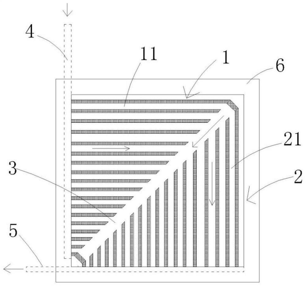
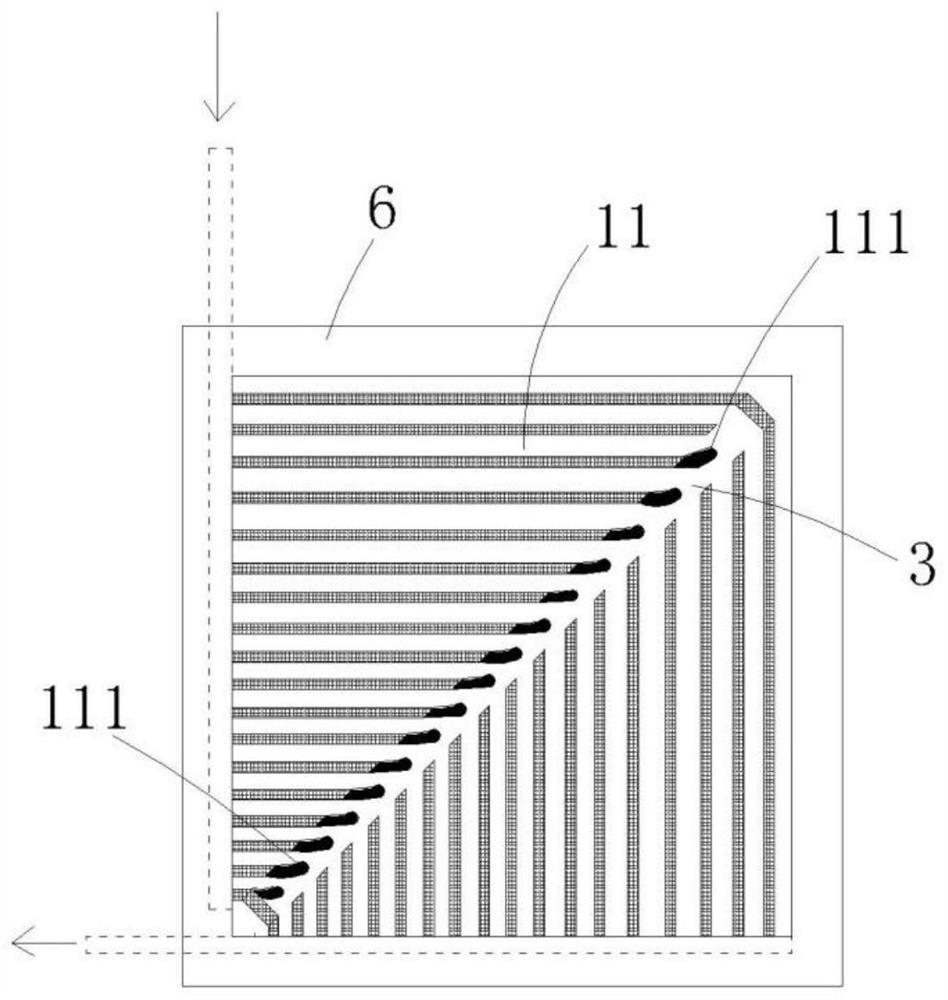
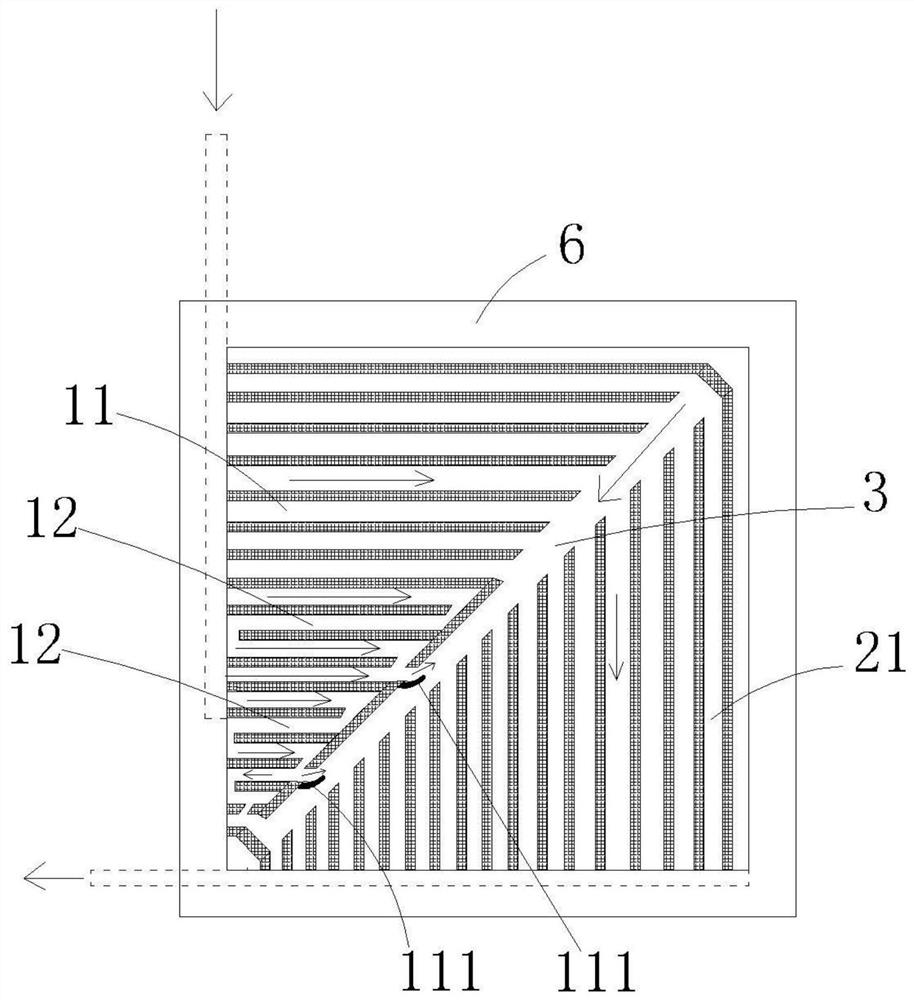
[0026] The implementation of the present invention will be illustrated by specific specific examples below, and those skilled in the art can easily understand other advantages and effects of the present invention from the contents disclosed in this specification.

[0027] see Figure 1 to Figure 3 . It should be noted that the structures, proportions, sizes, etc. shown in the drawings of this specification are only used to match the content disclosed in the specification, for those who are familiar with this technology to understand and read, and are not used to limit the conditions for the implementation of the present invention , so it has no technical substantive meaning, and any modification of structure, change of proportional relationship or adjustment of size shall still fall within the scope of the disclosure of the present invention without affecting the functions and objectives of the present invention. within the range covered by the technical content. At the same...


PUM


Abstract

The invention provides a fuel cell flow channel structure, a flow field plate and a fuel cell, which are used for solving the problems of flow channel water accumulation and poor cell stability of thefuel cell in the prior art. The fuel cell flow channel structure comprises an upper triangular area and a lower triangular area; the upper triangular area is provided with plurality of horizontal flow channels, and in every two vertically adjacent horizontal flow channels, length of the upper horizontal flow channel is larger than that of the lower horizontal flow channel; the lower triangular area is provided with a plurality of vertical flow channels; the vertical flow channels and the horizontal flow channels correspond to one another to form L-shaped flow channels, and the longer verticalflow channels correspond to the longer horizontal flow channels; each horizontal flow channel and one end far away from the lower triangular area are respectively communicated with an inlet pipeline;the ends, away from the upper triangular area, of the vertical flow channels communicate with an outlet pipeline; the fuel cell flow channel structure comprises an oblique angle flow channel which islocated between the upper triangular area and the lower triangular area, and the horizontal flow channels and the vertical flow channels are communicated with the oblique angle flow channel.

Description

technical field [0001] The invention relates to the field of new energy batteries, in particular to a fuel cell flow channel structure, a flow field plate and a fuel cell. Background technique [0002] Proton exchange membrane fuel cell is considered as an ideal power source suitable for human development and environmental requirements due to its advantages of high efficiency, high energy and low pollution. The bipolar plate (flow field plate) is an important part of the proton exchange membrane fuel electromagnetic, and its mass accounts for more than 60% of the battery stack. The flow channel design on the flow field plate has a great impact on battery performance, operating efficiency, and manufacturing cost. [0003] The flow channels of the existing flow field plates include serpentine flow channels, parallel flow channels, multi-channel serpentine flow channels, spiral flow channels, metal mesh flow channels, foam material flow channels, etc. The problems existing in ...

Claims


Application Information

Patent Timeline
Patent Type & Authority Applications(China)
IPC IPC(8): H01M8/0258H01M8/026H01M8/0263
CPCH01M8/0258H01M8/026H01M8/0263Y02E60/50Y02P70/50
Inventor 欧阳春周小卫
Owner JIANGSU UNIV OF SCI & TECH
Why Eureka
Try Eureka