Automatic valve closing device for solar water heater overflow

A solar water heater and valve device technology, which is applied to solar collectors, solar collector safety, solar collector controllers, etc., can solve problems such as failure to close valves in time, increase safety and reliability, and save Water resource, effect of increasing reliability

Inactive Publication Date: 2020-06-26
汤小兰
View PDF0 Cites 0 Cited by
  • Summary
  • Abstract
  • Description
  • Claims
  • Application Information

AI Technical Summary

Problems solved by technology

[0004] The purpose of the present invention is to solve the disadvantages in the prior art that the user manually closes the valve and cannot close the valve in time, and proposes a solar water heater overflow automatic valve closing device

Method used


Image

  • Automatic valve closing device for solar water heater overflow
  • Automatic valve closing device for solar water heater overflow
  • Automatic valve closing device for solar water heater overflow

Examples


Embodiment 1

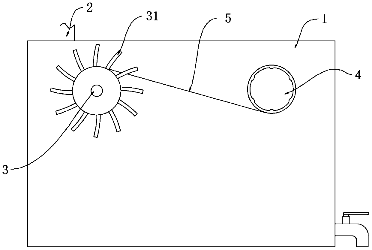
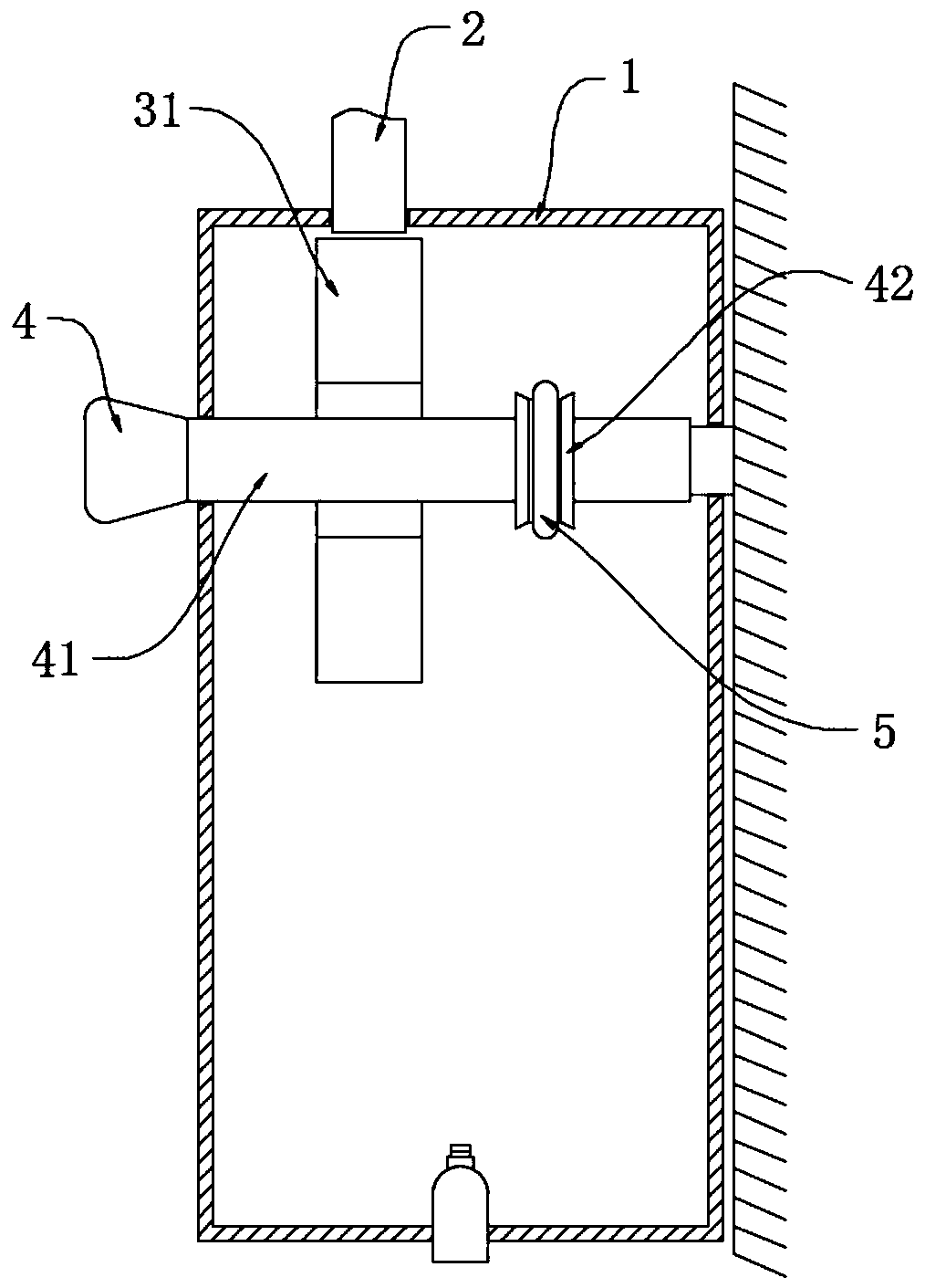
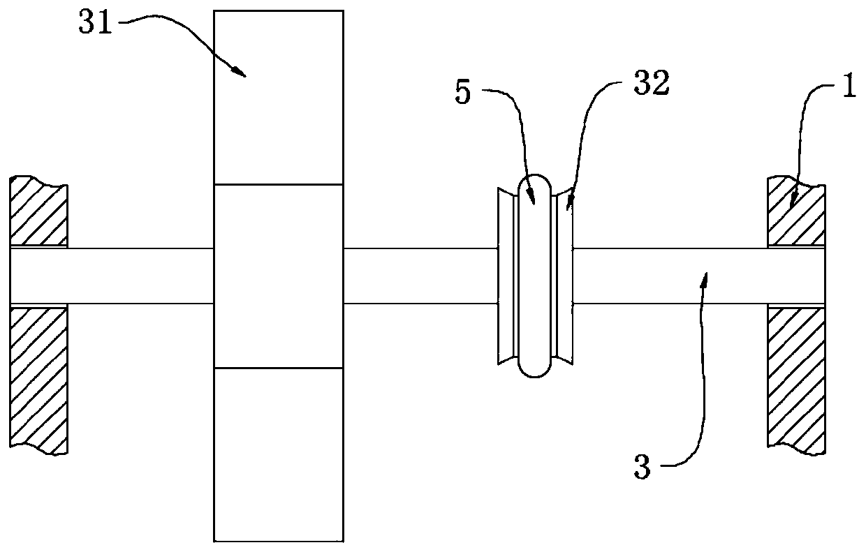
[0026] refer to Figure 1-3 , a solar water heater overflow automatic valve closing device, including a water tank 1 fixed on the wall, an overflow pipe 2 and an upper water pipe, a rotating shaft 3 is installed in the water tank 1, and a water valve pipe is installed on the upper water pipe extending into the water tank 1 and rotated 41. The water valve pipe 41 extends to the outside of the water tank 1 and is equipped with a water valve knob 4. A passive adjustment wheel 42 is fixedly installed on the water valve pipe 41. A water wheel 31 is fixedly installed on one end of the rotating shaft 3, and the water wheel 31 is located in the overflow pipe. 2, the other end of the rotating shaft 3 is rotated with an active adjustment wheel 32, and the active adjustment wheel 32 and the passive adjustment wheel 42 are jointly equipped with an adjustment chain 5;

[0027] After the solar water heater is full of water, continue to add water and discharge it from the overflow pipe 2. Th...

Embodiment 2

[0032] refer to Figure 4-5 , a solar water heater overflow automatic valve closing device, which is basically consistent with Embodiment 1, the difference is that:

[0033] A power box 6 is fixedly installed on the outer wall of the water tank 1, and one end of the rotating shaft 3 extends into the power box 6 and a disc generator 61 is fixedly installed therein. A storage battery 63 is fixedly installed in the power box 6. The water supply indicator light 62, the water storage indicator light 64 and the buzzer 65 are installed, and the first conductive rod 66 and the second conductive rod 67 are fixedly installed on the inner wall of the water tank 1, and the lower end of the first conductive rod 66 is higher than the first conductive rod 66. The lower ends of the two conductive rods 67.

[0034] The output terminal of the disc generator 61 is electrically connected to the charging terminal of the water filling indicator light 62 and the battery 63 respectively, the water f...


PUM


Abstract

The invention discloses an automatic valve closing device for solar water heater overflow. The automatic valve closing device for solar water heater overflow comprises a water tank, an overflow pipe and a water feeding pipe, wherein the water tank, the overflow pipe and the water feeding pipe are fixed to the wall, a rotating shaft is rotatably installed in the water tank, the water feeding pipe extends into the water tank and is rotatably provided with water valve pipe, the water valve pipe extends to the outside of the water tank and is provided with a water valve knob, a driven adjustment wheel is fixedly installed on the water valve pipe, a water wheel is fixedly installed at one end of the rotating shaft, the water wheel is located under the overflow pipe, a driving adjustment wheelis rotatably installed at the other end of the rotating shaft. The gravitational potential energy of water in the overflow pipe is converted into rotating mechanical energy through the water wheel andthe rotating shaft, and the driven adjustment wheel is driven by the driving adjustment wheel and an adjustment chain to rotate the water valve pipe to close the water feeding pipe to stop water feeding, the speed of water closing and the reliability of the device are improved, and the device remind the user to check the water closing effect again through a water feeding circuit and remind the user to drain through a water storage circuit, iand the convenience and safety of the device are improved.

Description

technical field [0001] The invention relates to the field of solar water heaters, in particular to an overflow automatic valve closing device for solar water heaters. Background technique [0002] Solar water heaters heat the water stored inside by light energy, which saves electricity. However, when using solar water heaters for households, water needs to be filled into the solar water heaters every time. When the water in the solar water heaters is filled and continues to add water, the excess water will be lost It flows from the overflow hole and is discharged with the overflow pipe. [0003] In existing solar water heaters, the shut-off valve usually closes the water supply valve after the user hears the sound of water flowing out of the overflow pipe, and cannot go to the water valve to close the water valve in time, resulting in a waste of water resources. Contents of the invention [0004] The purpose of the present invention is to solve the disadvantages in the pr...

Claims


Application Information

Patent Timeline
Patent Type & Authority Applications(China)
IPC IPC(8): F24S50/00F24S40/60F03B1/00F03B7/00F03B11/00
CPCF03B1/00F03B7/00F03B11/004F24S40/60F24S50/00Y02E10/20Y02E10/40
Inventor 汤小兰
Owner 汤小兰
Why Eureka
Try Eureka