Near-field radiation attenuation test method and three-dimensional display system

A near-field radiation and three-dimensional display technology, which is applied in the transmission system, image data processing, transmission monitoring, etc., can solve the problems not given and achieve the effect of easy legibility

Active Publication Date: 2020-09-18
NAT UNIV OF DEFENSE TECH
View PDF13 Cites 6 Cited by
  • Summary
  • Abstract
  • Description
  • Claims
  • Application Information

AI Technical Summary

Problems solved by technology

[0006] To sum up, the existing technology has not provided a technology based on a three-dimensional geographic information platform. Through the powerful data management and data analysis functions of the geographic information s

Method used


Image

  • Near-field radiation attenuation test method and three-dimensional display system
  • Near-field radiation attenuation test method and three-dimensional display system
  • Near-field radiation attenuation test method and three-dimensional display system

Examples


Embodiment 1

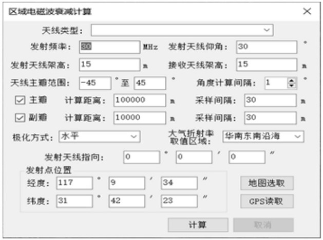
[0139] Embodiment 1, calculation of near-field radiation area, image 3 Radiation area radio wave attenuation calculation.

[0140] The specific implementation process is:

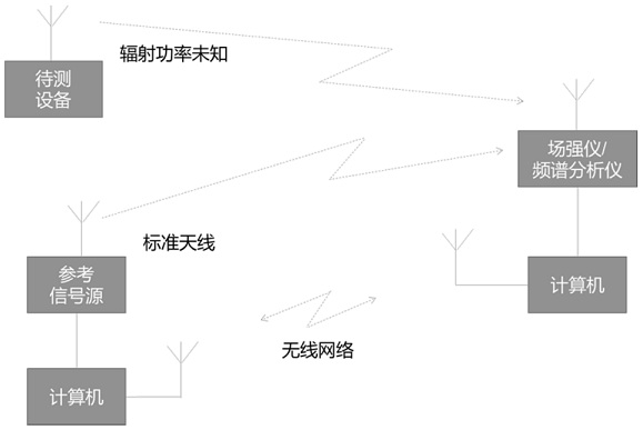
[0141] Set the transmitting and receiving antenna parameters, such as transmitting frequency, transmitting antenna elevation angle, transmitting antenna height, transmitting antenna position, transmitting antenna orientation, transmitting antenna polarization mode, receiving antenna height, antenna main lobe range, where the transmitting point position can be set by Acquired by an external GPS device or specified on a three-dimensional earth.

[0142] Set calculation parameters, such as angle calculation interval, main lobe calculation distance, side lobe calculation distance, atmospheric refraction index, etc.

[0143] The calculation software automatically generates the propagation path according to the given angle interval and calculation distance according to the angle range of the main and side lobe...

Embodiment 2

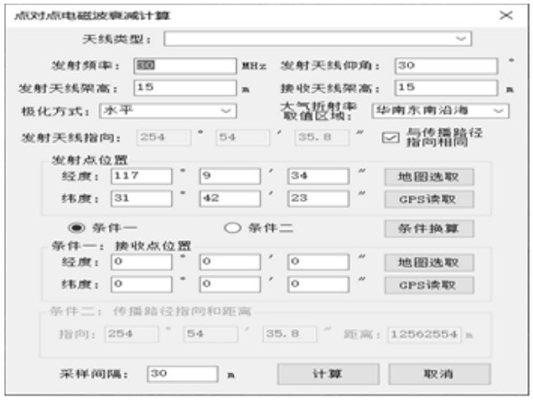
[0147] Embodiment 2, point-to-point radiation attenuation calculation, Figure 4 Point-to-point radio wave radiation attenuation calculation.

[0148] The specific implementation process of the point-to-point radiation attenuation calculation is similar to that of the radiation area attenuation calculation, the difference is that the point-to-point radiation attenuation calculation only needs to calculate one propagation path, and the propagation path can be given in two ways: the first is to directly specify the transmitting point and receiving point The other is to specify the location of the launch point, the direction and distance of the propagation path.

[0149] The basic process is the same as above, the difference is that only one ray is calculated here.

Embodiment 3

[0150] Embodiment 3, calculation result visualization,

[0151] Figure 5 Radiation area attenuation visualization, calculation result visualization includes two aspects:

[0152] One is the visualization of the overall attenuation of the radiation area, which is also a major difficulty of this software, because there are usually millions of attenuation values ​​calculated. If you follow the usual practice, you need to form an isosurface with millions of points Coloring, the amount of calculation is huge, and the amount of graphics generated at the same time cannot be carried by the basic 3D GIS platform. To solve this problem, this software creatively rasterizes the numerical points, and then realizes the overall visual display of the region in the form of raster data Speed ​​and efficiency have been qualitatively improved.

[0153] Step 1: The software will calculate the boundary graph of the calculation area and the maximum circumscribing rectangle of the graph based on t...


PUM


Abstract

The invention provides a near-field radiation attenuation test method and device. The method comprises steps of using a unique geographic large-scale scene three-dimensional visualization technology of a three-dimensional geographic information system; fusing a satellite image base map and elevation model data; establishing a virtual digital earth display platform; meanwhile, configuring a three-dimensional visualization scheme of an electric wave propagation radiation attenuation calculation result; on a virtual digital earth platform, carrying out three-dimensional visual display through geographic position mapping in a vivid, attractive, easy-to-distinguish, easy-to-read and measurable mode, integrating nationwide elevation model data and surface coverage data, and using an efficient data query engine for providing data support for radio wave propagation radiation attenuation calculation; various data calling interfaces are unified, standardized access of an external radiation attenuation scientific calculation module is realized, and a unified radio wave transmission radiation attenuation calculation platform is established.

Description

technical field [0001] The invention belongs to the technical field of radio frequency radiation testing, in particular to a near-field radiation attenuation testing method and device. Background technique [0002] Radio wave propagation has always been one of the most widely concerned and researched directions in the field of engineering electromagnetic field theory and environmental electromagnetic characteristics research. Due to the complexity of the surface characteristics, the propagation of radio waves on the surface is a problem of radio wave propagation in a complex environment. Different propagation mechanisms such as reflection, refraction, diffraction, transmission and scattering will appear when propagating in undulating terrain such as mountains, hills and tall buildings. Due to the great randomness of the occurrence of these mechanisms, it is quite difficult to accurately predict the propagation characteristics of radio waves in complex environments. [0003...

Claims


Application Information

Patent Timeline
IPC IPC(8): H04W24/06H04B17/391G06T17/00
CPCG06T17/00H04W24/06H04B17/3913
Inventor 吴微露储飞黄许军俞红兵位林营许士敏李昂瞿洋毕大庆
Owner NAT UNIV OF DEFENSE TECH
Why Eureka
Try Eureka