A near-field radiation attenuation test method and three-dimensional display system
A near-field radiation, three-dimensional display technology, used in transmission systems, transmission monitoring, instruments, etc., can solve the problem of not giving, and achieve the effect of easy to read
- Summary
- Abstract
- Description
- Claims
- Application Information
AI Technical Summary
Problems solved by technology
Method used
Image
Examples
Embodiment 1
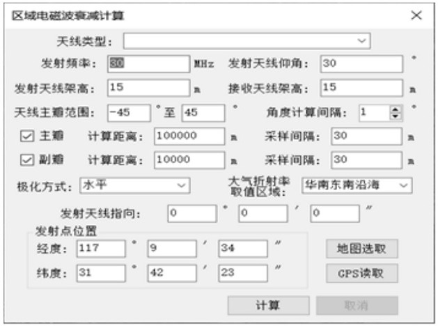
[0139] Embodiment 1, calculation of near-field radiation area, image 3 Radiation area radio wave attenuation calculation.
[0140] The specific implementation process is:
[0141] Set the transmitting and receiving antenna parameters, such as transmitting frequency, transmitting antenna elevation angle, transmitting antenna height, transmitting antenna position, transmitting antenna orientation, transmitting antenna polarization mode, receiving antenna height, antenna main lobe range, where the transmitting point position can be set by Acquired by an external GPS device or specified on a three-dimensional earth.
[0142] Set calculation parameters, such as angle calculation interval, main lobe calculation distance, side lobe calculation distance, atmospheric refraction index, etc.
[0143] The calculation software automatically generates the propagation path according to the given angle interval and calculation distance according to the angle range of the main and side lobe...
Embodiment 2
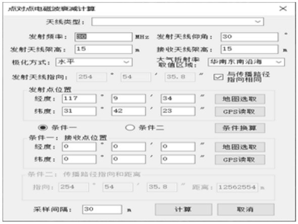
[0147] Embodiment 2, point-to-point radiation attenuation calculation, Figure 4 Point-to-point radio wave radiation attenuation calculation.
[0148] The specific implementation process of the point-to-point radiation attenuation calculation is similar to that of the radiation area attenuation calculation, the difference is that the point-to-point radiation attenuation calculation only needs to calculate one propagation path, and the propagation path can be given in two ways: the first is to directly specify the transmitting point and receiving point The other is to specify the location of the launch point, the direction and distance of the propagation path.
[0149] The basic process is the same as above, the difference is that only one ray is calculated here.
Embodiment 3
[0150] Embodiment 3, calculation result visualization,
[0151] Figure 5 Radiation area attenuation visualization, calculation result visualization includes two aspects:
[0152] One is the visualization of the overall attenuation of the radiation area, which is also a major difficulty of this software, because there are usually millions of attenuation values calculated. If you follow the usual practice, you need to form an isosurface with millions of points Coloring, the amount of calculation is huge, and the amount of graphics generated at the same time cannot be carried by the basic 3D GIS platform. To solve this problem, this software creatively rasterizes the numerical points, and then realizes the overall visual display of the region in the form of raster data Speed and efficiency have been qualitatively improved.
[0153] Step 1: The software will calculate the boundary graph of the calculation area and the maximum circumscribing rectangle of the graph based on t...
PUM
 Abstract
Description
Claims
Application Information
 - R&D
- Intellectual Property
- Life Sciences
- Materials
- Tech Scout
- Unparalleled Data Quality
- Higher Quality Content
- 60% Fewer Hallucinations
Browse by: Latest US Patents, China's latest patents, Technical Efficacy Thesaurus, Application Domain, Technology Topic, Popular Technical Reports.
© 2025 PatSnap. All rights reserved.Legal|Privacy policy|Modern Slavery Act Transparency Statement|Sitemap|About US| Contact US: help@patsnap.com


