Preparation method of rigid-flex printed circuit board with blind groove

A technology of rigid-flex boards and blind slots, which is applied in multi-layer circuit manufacturing, printed circuit manufacturing, electrical components, etc., can solve the problems that rigid-flex boards can't achieve the effect, and blind slots can't be combined with rigid-flex boards at the same time. Achieve the effect of simple operation, high efficiency and reducing glue overflow

Active Publication Date: 2020-09-18
珠海杰赛科技有限公司 +1
View PDF4 Cites 7 Cited by
  • Summary
  • Abstract
  • Description
  • Claims
  • Application Information

AI Technical Summary

Problems solved by technology

In the production process, there is a problem that blind slots and rigid-flexible combinations cannot be taken into account at the same time, and the rigid-flexible combination boards produced cannot achieve the expected effect

Method used


Image

  • Preparation method of rigid-flex printed circuit board with blind groove
  • Preparation method of rigid-flex printed circuit board with blind groove
  • Preparation method of rigid-flex printed circuit board with blind groove

Examples


Embodiment 1

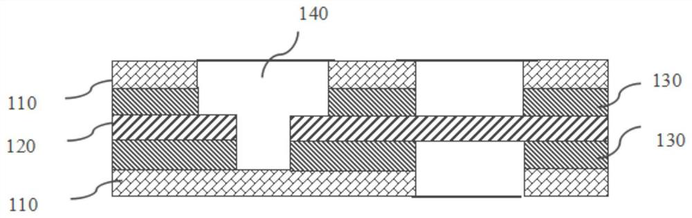
[0038] A rigid-flex combination plate with blind slots, the structure of the combination plate is shown in figure 1 , from top to bottom, followed by a rigid board 110, a prepreg 130, a flexible board 120, a prepreg 130, and a rigid board 110, and the combined board has a blind slot 140 spanning the rigid board and the flexible board.

[0039] The preparation method of the rigid-flex board comprises the following steps:

[0040] The expansion and contraction of the flexible board is measured for the first time to obtain the expansion and contraction coefficient of the covering film, and then the covering film is grafted on the flexible board and pressed together, and then the expansion and contraction of the flexible board is measured for the second time, and finally the deflection is milled out. The position of the blind groove on the sex plate;

[0041] (1) Take the flexible board, cut the material, make the inner layer circuit on the flexible board, and check the quality o...

Embodiment 2

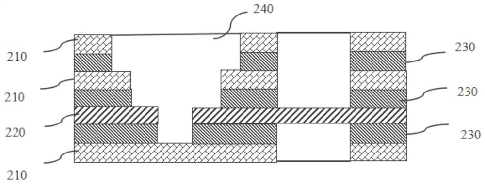
[0048] A rigid-flex combined board with blind slots, see the structure of the combined board figure 2 , from top to bottom, followed by rigid board 210, prepreg 230, rigid board 210, prepreg 230, flexible board 220, prepreg 230, rigid board 210, the combination board has a blind slot 240 spanning the rigid and flexible boards.

[0049] The preparation method of the rigid-flex board comprises the following steps:

[0050] (1) Take the flexible board, cut the material, make the inner layer circuit on the flexible board, and check the quality of the PCB circuit pattern through optical scanning; measure the expansion and contraction of the flexible board for the first time to obtain the expansion and contraction of the cover film Coefficient, film exposure, gold-plated protection for the bottom of the blind groove, film removal, blackening, grafting cover film, quick pressing, and baking board; then perform a second expansion and contraction measurement on the flexible board to m...


PUM


Abstract

The invention belongs to the technical field of printed circuit boards, and discloses a preparation method of a rigid-flexible printed circuit board with a blind groove. The method comprises the following steps: (1) manufacturing a flexible board, and milling the position of the blind groove on the flexible board; (2) manufacturing a rigid plate, and milling the position of a blind groove in the rigid plate; (3) manufacturing prepregs, and milling blind groove positions and flexible areas on the prepregs; (4) stacking the rigid plate prepared in the step (2), the prepreg prepared in the step (3) and the flexible plate prepared in the step (1) in a staggered manner, respectively plugging blocking films in blind grooves of the rigid plate, the flexible plate and the prepreg, and performing laminating; (5) manufacturing an outer layer circuit; (6) performing hole milling and cover opening. By adopting the preparation method of the rigid-flex printed circuit board, the rigid-flex printed circuit board with the blind groove spanning over can be prepared, and the combination of the blind groove and the rigid-flex printed circuit board is realized; and the prepared rigid-flex printed circuit board has the blind slot excessive glue of less than or equal to 0.5 mm and the flatness of less than or equal to 0.1 mm.

Description

technical field [0001] The invention belongs to the technical field of printed circuit boards, in particular to a method for preparing a rigid-flex board with blind slots. Background technique [0002] With the development of printed circuit boards (PCB for short) in the direction of small size, light weight, three-dimensional installation and high connection reliability, rigid-flexible printed boards have become one of the main growth points of the PCB industry in the future. one. [0003] At present, rigid-flex printed boards in the industry are rigid core board, PP adhesive layer, flexible core board, PP adhesive layer, and rigid core board from top to bottom. Usually, the flexible core board is in the middle. The structure of the rigid core board on both sides, in which multiple rigid core boards can be used, and multiple flexible core boards can also be used, that is, the layers can be 3-N layers (the minimum layer is three layers, and the rigid layer-PP adhesive layer...

Claims


Application Information

Patent Timeline
Patent Type & Authority Applications(China)
IPC IPC(8): H05K3/46
CPCH05K3/4691H05K2203/0214
Inventor 郑伟生黄德业关志锋
Owner 珠海杰赛科技有限公司
Why Eureka
Try Eureka