Dynamic unbalanced force adjustment system and geotechnical centrifuge

A technology of adjusting system and balancing force, applied in centrifuges and other directions, can solve the problems of lack of reversible adjustment ability, slow trim response speed, and inability to reverse return, so as to improve the trim ability and trim efficiency, and reduce the air supply pressure and supply. Gas volume indicator, fast response effect

Pending Publication Date: 2020-09-22
GENERAL ENG RES INST CHINA ACAD OF ENG PHYSICS
View PDF4 Cites 2 Cited by
  • Summary
  • Abstract
  • Description
  • Claims
  • Application Information

AI Technical Summary

Problems solved by technology

This method based on moving the trim mass has a slow trim response speed and very limited trim capability, and this drive system is difficult to work reliably in a large centrifugal field with a high G value
[0004] Patent 201320405085.2 "New Balance Self-Adjusting System for Geotechnical Centrifuge" and patent 201810843902.X "Dynamic Balance Adjustment System for Geotechnical Centrifuge" disclose the method of using the additional centrifugal force generated by water under the centrifugal field to achieve dynamic balance, but this liquid-based The trim method of autonomous flow under the centrifugal field has a large trim error, and the water can only be released in one direction and cannot be returned in the opposite direction. It does not have reversible adjustment ability, and its trim ability is relatively limited.

Method used


Image

  • Dynamic unbalanced force adjustment system and geotechnical centrifuge
  • Dynamic unbalanced force adjustment system and geotechnical centrifuge
  • Dynamic unbalanced force adjustment system and geotechnical centrifuge

Examples


Embodiment Construction

[0028] In order to make the object, technical solution and advantages of the present invention more clear, the present invention will be further described in detail below in conjunction with the accompanying drawings and embodiments. It should be understood that the specific embodiments described here are only used to explain the present invention, and are not intended to limit the present invention, that is, the described embodiments are only some of the embodiments of the present invention, but not all of the embodiments. The components of the embodiments of the invention generally described and illustrated in the figures herein may be arranged and designed in a variety of different configurations.

[0029] Accordingly, the following detailed description of the embodiments of the invention provided in the accompanying drawings is not intended to limit the scope of the claimed invention, but merely represents selected embodiments of the invention. Based on the embodiments of ...


PUM


Abstract

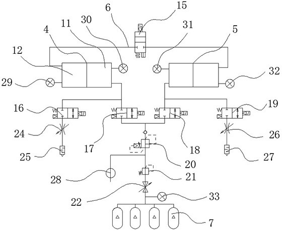
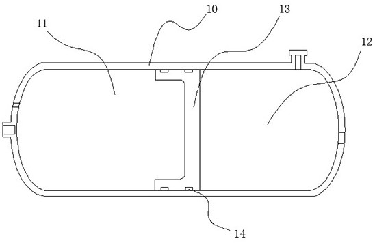
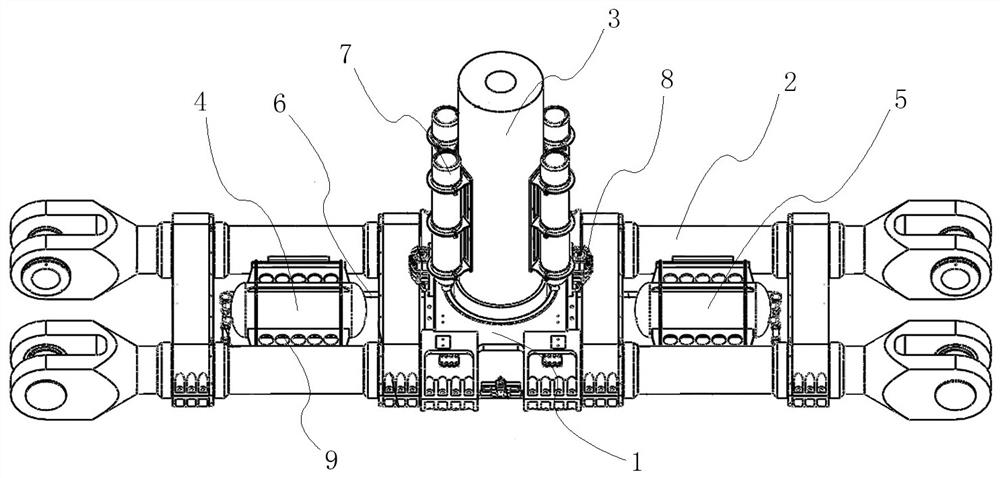
The invention relates to the technical field of centrifuge balancing, and specifically discloses a dynamic unbalanced force adjustment system and a geotechnical centrifuge. The dynamic unbalanced force adjustment system comprises a first pressure vessel, a second pressure vessel, shells and a control unit, the first pressure vessel and the second pressure vessel are separately placed on two sidesof a rotating axis of a rotating device, the first pressure vessel and the second pressure vessel have the same structure, pistons which separate inner cavities of the shells to form gas cavities andliquid cavities are arranged in the shell, and the liquid cavity of the first pressure vessel communicates with the liquid cavity of the second pressure vessel through a communicating device pipeline;and the output end of the control unit communicates with the gas cavities of the first pressure vessel and the second pressure vessel. The dynamic unbalanced force adjustment system has the advantages that the total amount of liquid remains constant, and the gas pressure and gas volume in the pressure vessels on two sides can be supplied and exhausted at the right time according to the demand, sothat the reciprocating trimming process has no cumulative effect and can realize reciprocating continuous reversibility adjusting.

Description

technical field [0001] The invention relates to the technical field of centrifuge balance, in particular to a dynamic unbalanced force adjustment system and a geotechnical centrifuge. Background technique [0002] During the normal operation of the geotechnical centrifuge, due to various factors such as the change of the center of mass of the test piece in the hanging basket, the unbalanced arm itself, etc., the centrifuge arm can generate slow / instantaneous loading and sustainable unbalanced force . When the unbalanced force exceeds a certain threshold, it will significantly deteriorate the stress state of the main shaft and key components of the equipment, aggravate the vibration, strain, noise, etc. of equipment operation, causing many adverse effects; excessive unbalanced force will force the centrifuge to enter The emergency braking shutdown state may directly lead to serious accidents such as the overturning of the centrifuge. Therefore, the dynamic trim system is an...

Claims


Application Information

Patent Timeline
Patent Type & Authority Applications(China)
IPC IPC(8): B04B13/00B04B15/00
CPCB04B13/00B04B13/003B04B15/00
Inventor 付兴陈磊冉光斌赵世鹏宋琼张志强
Owner GENERAL ENG RES INST CHINA ACAD OF ENG PHYSICS
Why Eureka
Try Eureka