
Technology for manufacturing and machining fiberglass reinforced plastic pipe fiberglass winding layer

A glass fiber and processing technology, which is applied in the field of glass fiber winding layer manufacturing and processing technology of glass fiber reinforced plastic pipes, can solve the problems of easily scratching the outer wall of glass fiber reinforced plastic pipes, and achieve the effect of reducing impact force and damage.

Inactive Publication Date: 2020-09-22
郭召勋
View PDF3 Cites 0 Cited by
  • Summary
  • Abstract
  • Description
  • Claims
  • Application Information

AI Technical Summary

Problems solved by technology

[0005] In order to solve the above problems, the present invention provides a manufacturing process for the glass fiber winding layer of FRP pipes, which can solve the problem that the traditional sheathing method usually sets the sheathing roller into the nozzle of the inner liner pipe, because the sheathing roller and the inner There may be a gap between the liners, and the existence of the gap often causes the sleeved inner liner to rotate synchronously when the casing roller rotates. When the two casing rollers withdraw from the two ends of the inner liner, the FRP pipe In the unclamped state, it falls rapidly under the action of gravity. When the lifting platform is not connected stably, it is easy to scratch the outer wall of the FRP pipe and other problems.

Method used


Image

  • Technology for manufacturing and machining fiberglass reinforced plastic pipe fiberglass winding layer
  • Technology for manufacturing and machining fiberglass reinforced plastic pipe fiberglass winding layer
  • Technology for manufacturing and machining fiberglass reinforced plastic pipe fiberglass winding layer

Examples


Embodiment Construction

[0037] In order to make the technical means, creative features, goals and effects achieved by the present invention easy to understand, the present invention will be further described below in conjunction with specific illustrations. It should be noted that, in the case of no conflict, the embodiments in the present application and the features in the embodiments can be combined with each other.

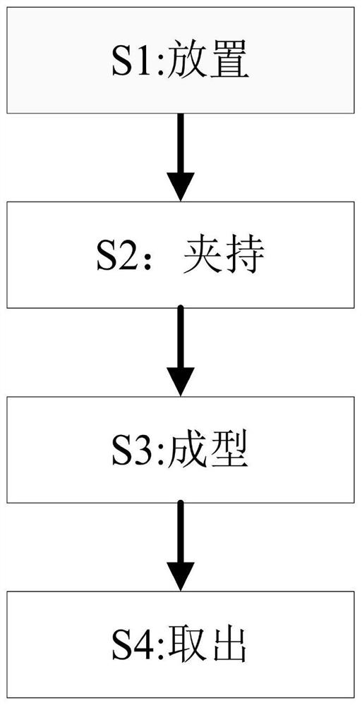
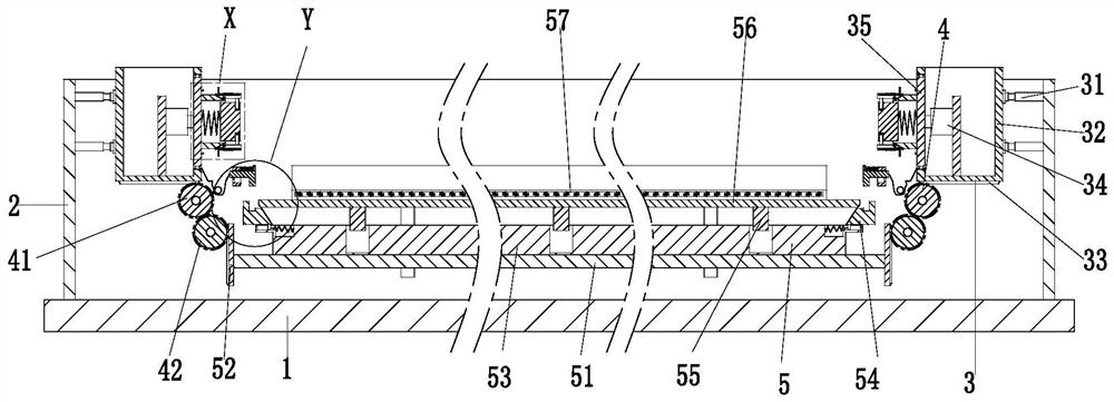
[0038] Such as Figure 1 to Figure 5 As shown, a glass fiber reinforced plastic pipe winding layer manufacturing process, which uses a clamping equipment, the clamping equipment includes a bottom plate 1, a frame 2, two clamping devices 3, two linkage devices 4 and a lifting Platform 5, using the above-mentioned clamping equipment to manufacture and process the glass fiber winding layer of the FRP pipe is as follows:

[0039]S1, placement: put the cured liner tube on the arc-shaped placement frame 57;

[0040] S2. Clamping: The cylinder 31 drives the two moving frames 32 to move to...


PUM


Abstract

The invention provides a technology for manufacturing and machining a fiberglass reinforced plastic pipe fiberglass winding layer. The technology is operation completed cooperatively by a baseplate, aframe body, two clamping devices, two linkage devices and a lifting platform. By means of the technology, problems that in a traditional sleeving arrangement manner, sleeving-arranged rollers are usually arranged inside the pipe orifice of a lining pipe in a sleeving manner, because gaps might exist between the sleeving-arranged rollers and the lining pipe, existence of the gaps frequently leadsto the condition that when the sleeving-arranged rollers rotate, the sleeving-arranged lining pipe cannot be driven to rotate synchronously; when the two sleeving-arranged rollers quit the two ends ofthe lining pipe, a fiberglass reinforced plastic pipe at his moment is in an unclamped state and falls at a high speed under the action of gravity; and when the pipe cannot be received steadily by the lifting table, the outer wall of the fiberglass reinforced plastic pipe is easy to scratch can be solved.

Description

technical field [0001] The invention relates to the field of manufacturing FRP pipes, in particular to a manufacturing process for glass fiber winding layers of FRP pipes. Background technique [0002] FRP pipe is a light, high-strength, corrosion-resistant non-metallic pipe. FRP pipe has the advantages of excellent corrosion resistance, long service life, light weight, convenient transportation and loading and unloading, and is often used in petroleum, chemical and drainage industries. During the production of FRP pipes, it is necessary to clamp the cured liner and drive it to rotate at a low speed, but some problems may be encountered during the clamping process: [0003] 1. Due to the large volume and heavy weight of the inner liner, usually the lifting platform lifts it up and clamps it by setting inner supports at both ends. The traditional way of setting is usually to set the set roller to the In the nozzle of the lining pipe, there may be a gap between the sleeve rol...

Claims


Application Information

Patent Timeline
Patent Type & Authority Applications(China)
IPC IPC(8): B29C70/68B29C70/78B29L23/00
CPCB29C70/681B29C70/78B29L2023/00
Inventor 郭召勋苏美琳
Owner 郭召勋
Learn More