
Automated stone plate stacking mechanism

A stacking and fossil technology, applied in the field of automatic stone slab stacking mechanism, can solve the problems of inconvenient operation and low processing efficiency of curved stone slabs, and achieve the effect of avoiding dumping and realizing support

Inactive Publication Date: 2020-09-22
王兰芳
View PDF0 Cites 7 Cited by
  • Summary
  • Abstract
  • Description
  • Claims
  • Application Information

AI Technical Summary

Problems solved by technology

[0002] Curved decorative stones are widely used in the market. For example, in buildings such as the main support columns in the lobby of large public buildings, in order to improve the aesthetics, they will be covered with curved stones, which can effectively improve the aesthetics and at the same time To avoid personal injury caused by the edges and corners on the support column, in the actual processing of the above-mentioned curved stone slabs, the entire base material is generally cut into multiple pieces by wire cutting equipment, and the wire cutting equipment cuts the base material During the process, the cutting line of the cutting device is arranged in the width direction of the substrate, and an arc-shaped gap is cut along the height direction of the substrate, and with the movement of the cutting device, the substrate is cut along the length direction. A gap between the adjacent gaps can form a curved stone plate, and then through manual knocking, the joint position between the curved stone plate and the base material can be hammered off to realize the separation of the curved stone plate. After the shaped stone slab is removed, the subsequent wire cutting equipment is used to cut the hammered position of the curved stone slab, so that the hammered position of the curved stone slab remains straight, and further processing of the curved stone slab is completed. After processing, in order to carry out the transfer of stone slabs, it is necessary to hoist the stone slabs to the storage rack one by one, so as to complete the storage and transfer of the curved stone slabs. In the subsequent processing of the above stone materials, there is always The problem of low processing efficiency, and the problem of inconvenient operation when the curved stone plate is actually clamped and cut

Method used


Image

  • Automated stone plate stacking mechanism
  • Automated stone plate stacking mechanism
  • Automated stone plate stacking mechanism

Examples


Embodiment Construction

[0027] In order to make the objects and advantages of the present invention clearer, the present invention will be described in detail below in conjunction with the examples. It should be understood that the following words are only used to describe one or several specific implementation modes of the present invention, and do not strictly limit the protection scope of the specific claims of the present invention. As used herein, the terms "parallel" and "perpendicular" are not limited to their strict geometric definitions, but include reasonable and inconsistent tolerances for machining or human error;

[0028] The automatic stone slab material stacking mechanism of the present invention will be described in detail below in conjunction with the entire building arc-shaped stone processing system:

[0029] Attached below Figure 1 to Figure 35 , the arc-shaped stone material processing system for construction of the present invention is described in detail:

[0030] A curved s...


PUM


Abstract

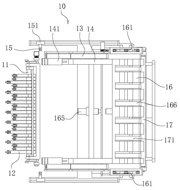
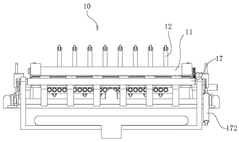
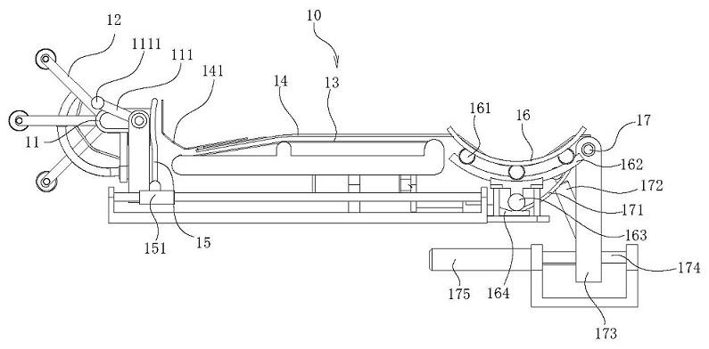
The invention relates to an automated stone plate stacking mechanism. The mechanism comprises a stacking rack, a convex block for clamping arc-shaped stone plates is arranged on the stacking rack, theconvex block forms sliding fit in the length direction of the stacking rack, the convex block is used to support the arc-shaped stone plates and openings are inclined downwards, and the convex blockas a whole is consistent with concave arc surface profiles of the arc-shaped stone plates, so that support for the arc-shaped stone plates can be effectively achieved, a stacking roller continuously leads a single arc-shaped stone plate to the convex block of the stacking rack, and support for the single arc-shaped stone plate is further achieved; with the placement of the arc-shaped stone plates,support for a plurality of arc-shaped stone plates is achieved, and when the convex block supports the arc-shaped stone plates, the opening ends of the arc-shaped stone plates are inclined downwards,so that support for the arc-shaped stone plates can be effectively achieved, and the falling problem of the arc-shaped stone plates is avoided.

Description

technical field [0001] The invention relates to the technical field of stone processing, in particular to an automatic stone slab material stacking mechanism. Background technique [0002] Curved decorative stones are widely used in the market. For example, in buildings such as the main support columns in the lobby of large public buildings, in order to improve the aesthetics, they will be covered with curved stones, which can effectively improve the aesthetics and at the same time To avoid personal injury caused by the edges and corners on the support column, in the actual processing of the above-mentioned curved stone slabs, the entire base material is generally cut into multiple pieces by wire cutting equipment, and the wire cutting equipment cuts the base material During the process, the cutting line of the cutting device is arranged in the width direction of the substrate, and an arc-shaped gap is cut along the height direction of the substrate, and with the movement of...

Claims


Application Information

Patent Timeline
IPC IPC(8): B65G47/52B65G47/34B65G47/24
CPCB65G47/24B65G47/34B65G47/52
Inventor 王兰芳辛冬群
Owner 王兰芳
Learn More