Blade edge passivating treatment device for electromechanical equipment accessory production

A technology of electromechanical equipment and passivation treatment, applied in the direction of metal material coating process, etc., can solve the problems of low efficiency, single structure, waste, etc., and achieve the effect of uniform distribution, avoiding pollution and avoiding waste

Inactive Publication Date: 2020-09-22
烟台福慧智能科技有限公司
View PDF0 Cites 2 Cited by
  • Summary
  • Abstract
  • Description
  • Claims
  • Application Information

AI Technical Summary

Problems solved by technology

[0004] Based on the technical problems that the existing passivation treatment device has a single structure, waste and low efficiency in passivati

Method used


Image

  • Blade edge passivating treatment device for electromechanical equipment accessory production
  • Blade edge passivating treatment device for electromechanical equipment accessory production
  • Blade edge passivating treatment device for electromechanical equipment accessory production

Examples


Embodiment 1

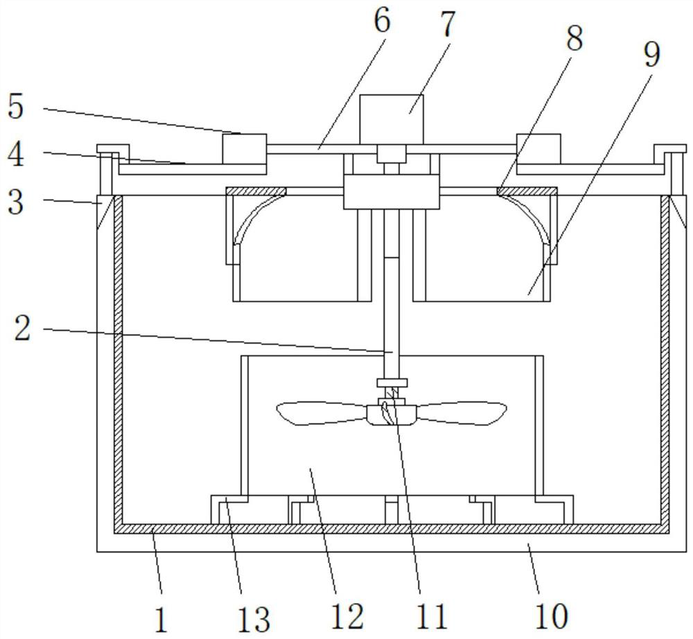
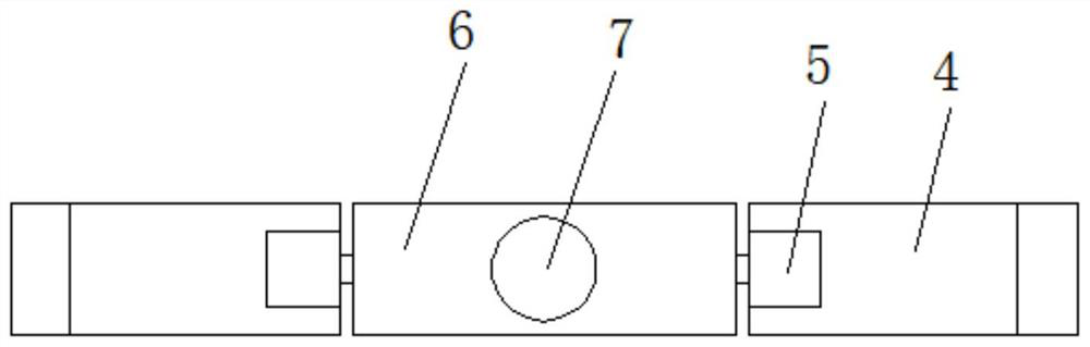
[0027] Reference Figure 1-4 , A blade edge passivation treatment device for the production of electromechanical equipment accessories, comprising a pool body 1. Electric push rods 3 are fixedly installed on both sides of the pool body 1, and a jacking plate 4 is fixedly installed on the top of the electric push rod 3, A stepping motor 5 is fixedly installed on the top of the two lifting plates 4, and a flipping plate 6 is fixedly installed between the output shafts of the two stepping motors 5, and a driving motor 7 is fixedly installed on the top of the flipping plate 6, and the driving A rotating rod 2 is fixedly installed at the bottom end of the output shaft of the motor 7, a mounting seat 11 is fixedly installed at the bottom end of the rotating rod 2, and a plurality of L-shaped support frames 13 are fixedly mounted on the bottom inner wall of the pool body 1, and the support frames 13 A slow-flow mechanism 12 is fixedly installed between the top ends of the device, a bru...

Embodiment 2

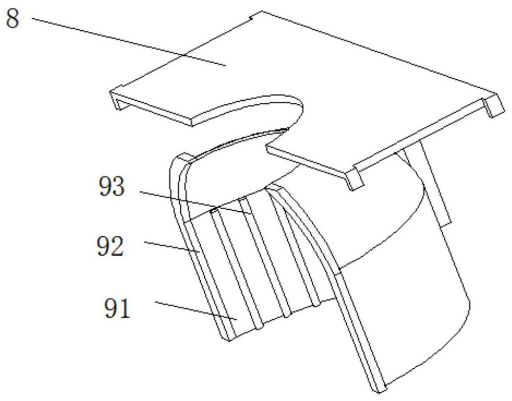
[0037] Reference Figure 1-3 with Figure 5 , A blade edge passivation treatment device for the production of electromechanical equipment accessories. Compared with the first embodiment, the slow flow mechanism 12 includes two fixed rings 125 distributed up and down, and the two fixed rings 125 are fixedly installed A plurality of baffle plates 124 arranged obliquely with arc-shaped structures, and a slow flow groove 123 provided between two adjacent baffle plates 124.

[0038] In this embodiment: when the blades in the device are rotating, the deflector 124 with the arc-shaped structure inclined to guide the solution, reduce the impact of the flowing solution, avoid splashing of the solution, and the solution passes gently inside the deflector 124 The flow trough 123 conducts flow diversion and slowly rotates around the inside of the pool body 1 to accelerate the effect of the passivation agent blending and make the passivation agent solution evenly distributed.


PUM


Abstract

The invention belongs to the technical field of electromechanical equipment accessory production, and particularly relates to a blade edge passivating treatment device for electromechanical equipmentaccessory production. Aiming at the problems that an existing passivating treatment device is simple in structure, wasting occurs during passivating treatment, and the efficiency is low, the followingscheme is provided, specifically, the blade edge passivating treatment device comprises a pool body, electric push rods are fixedly installed on the two sides of the pool body, jacking plates are fixedly installed at the top ends of the electric push rods, stepping motors are fixedly installed at the top ends of the two jacking plates, and a turnover plate is fixedly installed between output shafts of the two stepping motors. According to the blade edge passivating treatment device, a rotary rod and an installation seat are driven by a driving motor to rotate in the pool body, and accordingly, a passivator solution in the pool body is stirred, the passivating treatment quality is improved; and after passivating is finished, blades are taken out of the passivator solution and are driven bythe driving motor to rotate, accordingly, the solution adhering to the surfaces of the blades is removed through rotating, the drying speed of the passivator solution is increased, and the passivating treatment efficiency is improved.

Description

Technical field [0001] The invention relates to the technical field of production of mechanical and electrical equipment accessories, in particular to a blade edge passivation treatment device for the production of mechanical and electrical equipment accessories. Background technique [0002] Passivation treatment is the last process step in chemical cleaning, and is a key step. Its purpose is to prevent corrosion of materials. For example, after the boiler is pickled, washed with water, and rinsed, the metal surface is very clean, very activated and prone to corrosion. Therefore, passivation treatment must be carried out immediately to form a protective film on the cleaned metal surface to slow down corrosion. The main passivation mechanism is It can be explained by film theory, that is, it is believed that the passivation is due to the action of metal and oxidizing medium, and when it acts, a very thin, dense, good covering performance is formed on the metal surface, and it can...

Claims


Application Information

Patent Timeline
IPC IPC(8): C23C22/00C23C22/82
CPCC23C22/00C23C22/82
Inventor 郭守维
Owner 烟台福慧智能科技有限公司
Why Eureka
Try Eureka