
Plunger pump fluid end

A liquid end and plunger pump technology, applied in the field of plunger pump liquid end, can solve problems such as valve box cracking, valve box sealing surface wear, personal safety and operating efficiency, etc., to reduce stress and improve use Long life, simple and fast installation and disassembly

Pending Publication Date: 2020-09-22
YANTAI JEREH PETROLEUM EQUIP & TECH
View PDF0 Cites 103 Cited by
  • Summary
  • Abstract
  • Description
  • Claims
  • Application Information

AI Technical Summary

Problems solved by technology

During the operation, the main damage form of the fluid end is the cracking of the valve box and the wear of the sealing surface of the valve box. If the high-pressure liquid leaks, it will have a great impact on personal safety and operating efficiency

Method used


Image

  • Plunger pump fluid end
  • Plunger pump fluid end
  • Plunger pump fluid end

Examples


Embodiment Construction

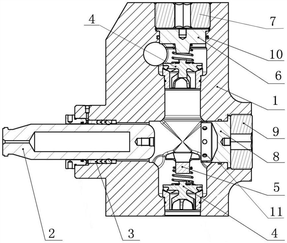
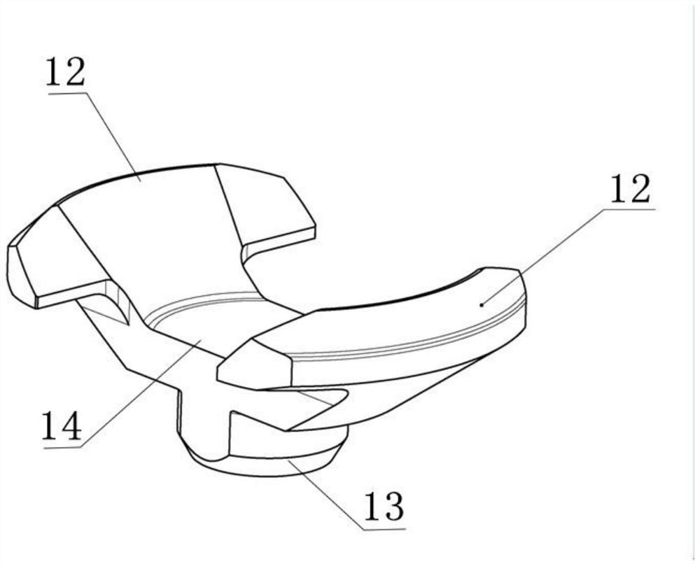
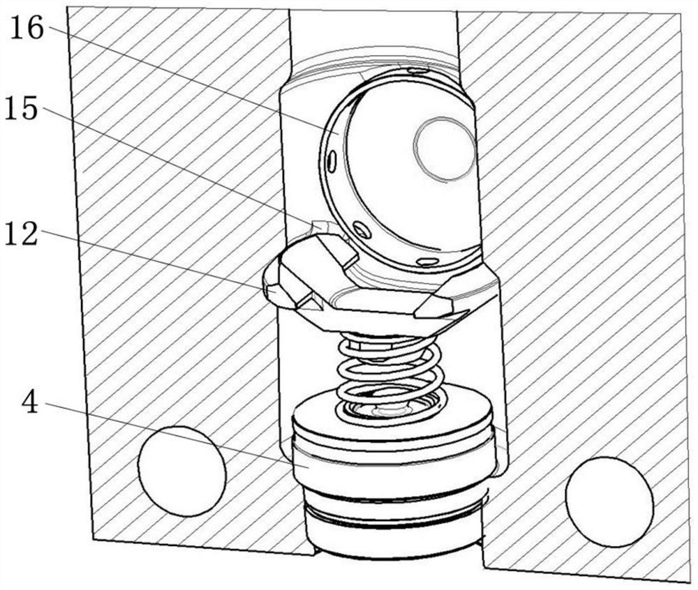
[0022] Such as Figures 1 to 4 As shown, a hydraulic end of a plunger pump includes a valve box 1, a plunger 2, a packing seal assembly 3, a valve assembly 4, a valve spring seat 5, a discharge gland 6, a discharge gland 7, The suction gland 8 and the suction gland 9 are provided with a suction cavity and a discharge cavity in the vertical direction inside the valve box 1, and a packing cavity and a suction gland 8 cavity in the horizontal direction inside the valve box 1. The valve assembly 4 and the valve spring seat 5 are set in the middle, and the valve assembly 4 and the valve spring seat 5 are connected. In the discharge cavity, the valve assembly 4, the discharge gland 6 and the discharge pressure cap are arranged in sequence from the inside to the outside. 7. The valve assembly 4 is connected with the discharge gland 6, and the discharge gland 7 is used to compress the discharge gland 6. In the packing cavity, the plunger 2 is sealed and connected with the valve box 1 ...


PUM


Abstract

The invention discloses a plunger pump fluid end. The plunger pump fluid end comprises a valve box, a plunger, a packing sealing assembly, a valve assembly, a valve spring seat, a discharge gland, a discharge pressing cap, a suction gland and a suction pressing cap, wherein the plunger, the packing sealing assembly, the valve assembly, the valve spring seat, the discharge gland, the suction glandand the suction pressing cap are arranged in the valve box; the valve spring seat comprises a bulge, a connecting piece and fins, the connecting piece is connected with the bulge and the fins respectively, and two fins are oppositely arranged; and a containing cavity is formed in the valve box and used for containing the fins. The plunger pump fluid end has beneficial effects that the mounting anddismounting are easier and faster by changing a structure of the valve spring seat and the mounting and fixing mode of the valve spring seat and the valve box, and meanwhile, the service life of thefluid end is prolonged. A plunger and the end surface of the suction gland are changed into cambered surfaces, so that internal fluid can flow conveniently. The valve spring seat can be prevented fromrotating left and right to fall off by additionally arranging the limiting bulge. A first sealing ring and a second sealing ring are both arranged on the valve box, so that abrasion is transferred toa quick-wear part, and the service life of the valve box is prolonged.

Description

technical field [0001] The invention relates to the technical field of a plunger pump liquid end, in particular to a plunger pump liquid end. Background technique [0002] At present, fracturing construction in oil and gas field exploitation is the main production stimulation method, in which the plunger pump is the core component of the entire fracturing equipment, and its service life needs to be continuously improved to meet the needs of long-term fracturing operations. The service life of the hydraulic end in the plunger pump is the key to the construction. The fracturing fluid or sand-carrying fluid enters through the low-pressure port of the hydraulic end, and the medium in the valve box of the hydraulic end is added to the pump during the reciprocating motion of the plunger. pressure, and enter the bottom of the well through the high-pressure pipeline. During the operation, the main damage forms of the fluid end are the cracking of the valve box and the wear of the s...

Claims


Application Information

Patent Timeline
IPC IPC(8): F04B9/10F04B53/10F04B53/14F04B53/00F04B53/22E21B43/26E21B43/267
CPCE21B43/26E21B43/267F04B9/10F04B53/00F04B53/10F04B53/109F04B53/14F04B53/143F04B53/22
Inventor 李晓斌姜琛郭子蒙李朋王继鑫李海龙
Owner YANTAI JEREH PETROLEUM EQUIP & TECH
Features
  • Generate Ideas
  • Intellectual Property
  • Life Sciences
  • Materials
  • Tech Scout
  • Unparalleled Data Quality
  • Higher Quality Content
  • 60% Fewer Hallucinations
Learn More