
Speed loss braking device for electric wheelchair transmission shaft

A technology of electric wheelchairs and braking devices, applied in the direction of automatic brakes, brake parts, brake types, etc., can solve the problems of operator's physical injury, fast speed, wheelchair rollover, etc., and achieve the effect of ensuring safety and speed

Inactive Publication Date: 2020-09-22
浙江火萌互娱信息技术有限公司
View PDF7 Cites 21 Cited by
  • Summary
  • Abstract
  • Description
  • Claims
  • Application Information

AI Technical Summary

Problems solved by technology

[0006] Aiming at the deficiencies of the prior art, the present invention provides a stall braking device for the transmission shaft of an electric wheelchair, which has the advantage of timely braking when the transmission shaft stalls, and solves the problem that the electric wheelchair still needs manual control, which makes it difficult to When the electric wheelchair is going downhill, it is prone to faster speed. If the operator fails to control the speed at this time, it is very likely that accidents such as wheelchair rollover will occur, which will cause the operator to suffer more serious physical injuries. injury problem

Method used


Image

  • Speed loss braking device for electric wheelchair transmission shaft
  • Speed loss braking device for electric wheelchair transmission shaft
  • Speed loss braking device for electric wheelchair transmission shaft

Examples


Embodiment Construction

[0024] The following will clearly and completely describe the technical solutions in the embodiments of the present invention with reference to the accompanying drawings in the embodiments of the present invention. Obviously, the described embodiments are only some, not all, embodiments of the present invention. Based on the embodiments of the present invention, all other embodiments obtained by persons of ordinary skill in the art without making creative efforts belong to the protection scope of the present invention.

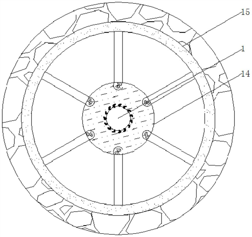
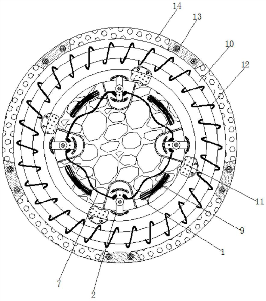
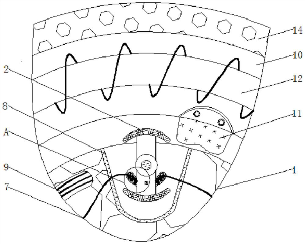
[0025] see Figure 1-4 , a stall braking device for the transmission shaft of an electric wheelchair, comprising a rotating shaft 1, a movable block 2 is movably connected to the outside of the rotating shaft 1, a movable groove is opened inside the rotating shaft 1, and the movable block 2 is movably connected to the inner side of the movable groove, The specification of the movable block 2 matches the specification of the movable groove, the inside of the mo...


PUM


Abstract

The invention relates to the technical field of aged-providing equipment and discloses a speed loss braking device for an electric wheelchair transmission shaft. The speed loss braking device for theelectric wheelchair transmission shaft comprises a rotary shaft. Moving blocks are movably connected outside the rotary shaft. Connecting plates are fixedly connected outside the moving blocks. Shellsare movably connected inside the rotary shaft. Springs are movably connected inside the shells. Electrorheological fluids are movably connected inside the shells. Electric wires are movably connectedinside the shells. Anticollision pads are movably connected inside the rotary shaft. Conductors are movably connected outside the rotary shaft. According to the speed loss braking device for the electric wheelchair transmission shaft, through interaction among the rotary shaft, the moving blocks, the connecting plates, the shells, the springs, the electrorheological fluids, the electric wires andthe anticollision pads, when the wheelchair travels normally and the rotating speed of the rotary shaft is normal, normal use of the wheelchair is not influenced; in this way, it can be avoided thatnormal use of the wheelchair is influenced because of speed limit, and the influence of a maximum-degree braking structure on the rotary shaft can be avoided; and in this manner, the device is more applicable to use under actual conditions.

Description

technical field [0001] The invention relates to the technical field of elderly care equipment, in particular to a stall braking device for a drive shaft of an electric wheelchair. Background technique [0002] As the elderly grow older, their physical functions are also declining, which will make the elderly need some elderly care equipment to assist their daily life, so as to avoid some serious physical injuries caused by accidents in their lives. [0003] People's increasing attention to the elderly has also promoted the development of elderly care equipment. The variety of elderly care equipment is also increasing, and the practicability of the elderly care equipment is also constantly suitable for the use of the elderly. Among the many elderly care equipment, wheelchairs It should be regarded as a relatively common type. The wheelchairs on the market are generally divided into electric and non-electric. Electric wheelchairs are favored by some elderly people with inconve...

Claims


Application Information

Patent Timeline
IPC IPC(8): F16D59/00F16D65/04F16D65/14A61G5/10A61G5/04F16D121/28
CPCA61G5/04A61G5/10F16D59/00F16D65/04F16D65/14F16D2121/28
Inventor 黄葵金
Owner 浙江火萌互娱信息技术有限公司
Learn More